Introduction
Designing a phased array antenna that scans the full azimuth sphere — 360 degrees continuously, without a motor — is one of the harder geometry problems in RF engineering. A linear array handles one scan plane well. A planar array covers a wide field of view but still faces the horizon. Neither solves the omnidirectional surveillance problem cleanly.
The uniform circular array (UCA) addresses this directly. By distributing radiating elements equally around a circle, the UCA creates a geometry designed specifically for full-azimuth electronic beam steering. Electronically steered antennas can switch beam directions in under 1 millisecond — a capability that mechanical rotation simply cannot match.
This article covers the operating principles behind UCAs, the design parameters that matter most, how they compare to other array geometries, and where they appear in real systems: from defense SIGINT receivers to LEO satellite terminals.
Key Takeaways
- A UCA places N elements at equal angular intervals around a circle, giving it inherent 360-degree azimuth scan symmetry
- Beam steering uses the circular array steering vector — not a simple linear phase ramp
- Element count is governed by the spatial Nyquist condition: N ≥ 2kR + 1
- UCAs trade peak gain for omnidirectional coverage; elevation steering requires stacked rings
- Applications span SIGINT/EW, LEO/MEO satcom tracking, GNSS null steering, and 5G base stations
What Is a Uniform Circular Array?
A UCA is an antenna array where N radiating elements are placed at equal angular intervals of 2π/N radians around the circumference of a circle with radius R. Each element sits at an angular position φₙ = 2πn/N for n = 0, 1, ..., N-1. That precise, regular spacing is what distinguishes a UCA from the broader category of "circular arrays," which may have irregular element placement.
The Array Factor and Phase Center
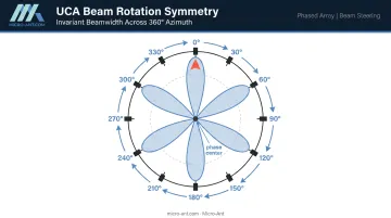
Each element contributes a phase-shifted version of the transmitted or received signal. These contributions combine to form a directional beam in space. Because every element lies at the same radial distance from the geometric center, the UCA has a naturally symmetric phase reference — the foundation for its full-azimuth scanning capability.
Ioannides and Balanis (IEEE, 2005) confirm that UCA symmetry allows patterns to be electronically rotated through 360 degrees with little change in beamwidth or sidelobe level. Linear and planar arrays cannot match this without mechanical repositioning or significant pattern degradation at off-broadside angles.
What a UCA Is Not
Three geometrically similar configurations are often conflated with UCAs:
- CDAA/Wullenweber arrays — the massive Cold War HF direction-finding structures like the AN/FRD-10 — are circularly disposed antenna arrays (CDAAs), not modern phased-array UCAs. The AN/FRD-10 used outer rings of 120 vertical elements operating from 9–30 MHz, with diameters exceeding 860 feet. These are passive HF monitoring infrastructures, architecturally and operationally distinct from phased-array UCAs.
- Cylindrical arrays stack multiple rings to add elevation aperture. Conformal arrays conform elements to a curved platform surface. Both share circular geometry principles with UCAs, but are architecturally distinct.
How UCAs Enable Beam Steering
The UCA steering vector uses terms of the form exp(ζ cos(φ − φₙ)), where ζ = ka sin(θ) and φₙ = 2πn/N. There is no simple progressive phase ramp across elements — the NRL explicitly notes that the UCA steering vector does not have progressive phase across elements as a linear array does.
Phase Mode Excitation and Beamforming
The preferred computational framework for UCA beamforming is phase mode excitation (PME) — a DFT-based approach where array patterns are synthesized as weighted sums of Fourier modes. A phase-mode vector has entries proportional to (1, wₘ, wₘ², ..., wₘᴺ⁻¹), where wₘ = exp(j·2πm/N). This structure allows efficient computation of steering weights and is the basis for DFT-based beamforming network architectures.
Zoltowski and Mathews formalized PME for direction finding with UCAs. The approach scales naturally to both analog phase shifter networks and digital beamforming implementations.
Elevation Scanning and Mutual Coupling
A single-ring UCA has a fundamental geometric limitation: elevation steering. The ring provides azimuthal aperture but no independent vertical aperture, so elevation performance is governed by the individual element pattern rather than a steerable array dimension. Wider elevation coverage requires stacked rings (cylindrical arrays) or hybrid planar-circular configurations.
Beyond geometry, the closed-ring structure introduces mutual coupling constraints:
- Adjacent and non-adjacent elements interact through near-field electromagnetic coupling, modifying sidelobe levels and radiation pattern shape
- Inter-element arc spacing near λ/2 is the standard starting point to balance coupling against grating lobe suppression
- Optimal spacing is determined through full-wave electromagnetic simulation for each specific design
Beam Squint in Wideband Systems
When fixed phase weights are applied across a wide instantaneous bandwidth, the electrical radius of the array (R/λ) changes with frequency. This causes beam peak drift with frequency — a phenomenon called beam squint. This is a critical consideration for wideband satcom and radar applications. Managing it requires either true-time-delay steering or wideband array architectures specifically designed to compensate for the frequency-dependent aperture scaling.
UCA vs. Other Array Geometries
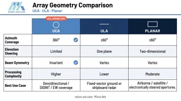
| Parameter | UCA | ULA | Planar (Rectangular) |
|---|---|---|---|
| Azimuth coverage | 360° continuous | ±60° from broadside | ±60° in two planes |
| Elevation steering | Limited (single ring) | One plane only | Two-dimensional |
| Beam symmetry | Invariant with azimuth rotation | Varies with scan angle | Varies with scan angle |
| Processing complexity | Higher (PME/DFT) | Lower | Moderate |
| Best use case | Omnidirectional surveillance, tracking | Single-sector high-gain | Wide-area 2D coverage |
Each geometry involves a direct tradeoff between coverage, gain, and processing overhead:
- UCA vs. ULA: A ULA achieves superior gain in a single scan plane with simpler signal processing, but cannot scan effectively beyond roughly ±60° from broadside. The UCA accepts some peak gain reduction in exchange for symmetric beam rotation across all azimuth directions.
- UCA vs. planar array: Planar arrays deliver high aperture gain and two-dimensional steering, yet still face a ±60° field-of-view constraint from boresight. The UCA is the stronger choice wherever full-azimuth or hemispherical coverage is required without physically rotating the aperture.
- Hybrid architectures: Cylindrical arrays — multiple stacked UCAs — combine azimuth coverage with meaningful elevation aperture, making them the logical next step when both dimensions carry equal weight.
Key Design Parameters for UCAs
Array Radius R
Radius determines the electrical size (R/λ), which controls achievable gain, half-power beamwidth, and the number of resolvable phase modes. The maximum supported mode order is approximately m_max = kR = (2π/λ)R. Larger R supports more phase modes and sharper beams, but it also increases mutual coupling complexity and physical footprint.
Number of Elements N
The spatial Nyquist condition for a UCA is N ≥ 2kR + 1, which translates to roughly N = (2πR)/(λ/2) for half-wavelength circumferential sampling. Too few elements cause spatial aliasing and grating lobes. Too many increases system cost and beamforming network complexity without proportional gain improvement.
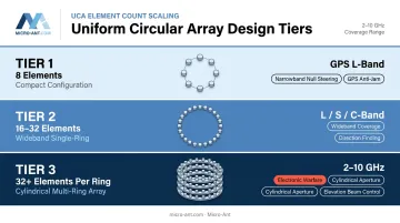
Practical designs range from:
- 8 elements — compact narrowband systems (GPS L-band null steering)
- 16–32 elements — wideband single-ring designs
- 32+ elements per ring — cylindrical arrays covering 2–10 GHz with elevation aperture
Element Type and Polarization
Element choice directly shapes the total radiation pattern (array factor × element pattern). For UCAs, broad-pattern elements are preferred — they maintain gain across the full azimuth scan range rather than rolling off as the beam rotates away from element boresight. Patch and dipole elements are common.
Element selection also shapes how well polarization is managed across the full scan range. As the beam rotates in azimuth, element orientation relative to the beam direction changes — making polarization control a demanding aspect of circular array design. Crossed-dipole or dual-polarized patch elements are standard choices for UCAs requiring polarization agility. A recent compact 6-element UCA at 3.55 GHz demonstrated circular polarization using dual-feed ring patches with a 90-degree feed phase difference, showing how element-level feed architecture directly addresses this geometry challenge.
Ground Plane and Radome Effects
A finite ground plane modifies the element pattern and introduces edge diffraction. A protective radome adds another layer of pattern perturbation. Both effects must be characterized through simulation and measured in a calibrated test environment — particularly on airborne and maritime platforms where size constraints limit ground plane dimensions.
Key factors requiring characterization include:
- Ground plane edge diffraction across the operational frequency band
- Radome dielectric loading and its effect on element impedance
- Combined pattern distortion under platform-specific size constraints
Applications of UCAs in Modern Systems
Defense, EW, and SIGINT
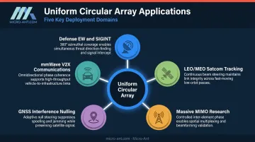
Electronic warfare and signals intelligence demand continuous 360-degree azimuth coverage — there is no acceptable substitute. UCAs are well-matched to direction-finding receivers, EW warning systems, and SIGINT collection payloads on airborne and shipborne platforms where signal source bearing is unknown and mechanical rotation is impractical.
A 7-element circular array at GPS L2 (1.2276 GHz) has been demonstrated for anti-jam null steering, capable of placing up to N-1 = 6 simultaneous nulls. The same geometry scales to UHF and S-band EW applications.
Satellite Communications: LEO and MEO Tracking
LEO and MEO tracking is the most active growth area for UCA and electronically steered array technology. The FCC has authorized SpaceX to deploy 7,500 additional Gen2 Starlink satellites, and Amazon's Kuiper constellation has received FCC authorization for its Ka-band NGSO system. As LEO and MEO constellations proliferate, terminals must hand over continuously between satellites crossing the sky — without mechanical rotation.
UCAs support this continuous handover by steering electronically across the full azimuth horizon. For wideband satcom, the challenge is managing beam squint across the operating band while maintaining link margin throughout the handover arc.
Micro-Ant, which serves satcom operators including SES O3B, Eutelsat, Intelsat, Inmarsat, and Iridium, has developed custom phased array antenna systems for this market, including Ka-band designs that earned the SatCom Technology of the Year Award for Most Innovative in 2022.
Their engineering process — built around AS9100:2016-certified design and in-house near-field test chambers operating from 750 MHz to 40 GHz — is directly applicable to the calibration and validation demands of electronically steered satcom apertures.
5G, GNSS, and Emerging Wireless
UCAs address several distinct requirements across emerging wireless applications:
- Massive MIMO research: Simultaneous multi-beam generation benefits directly from the angular symmetry that circular geometries provide.
- GNSS interference nulling: Circular arrays can reject jamming from any azimuth direction — critical for precision agriculture, autonomous vehicles, and defense navigation where the threat bearing is unknown.
- mmWave V2X communications: UCAs appear in vehicular beam-alignment literature as a practical topology for vehicle-to-everything connectivity at millimeter-wave frequencies.
Design Challenges and Engineering Trade-offs
Calibration at Scale
Maintaining precise amplitude and phase calibration across all N ports of a UCA — accounting for manufacturing tolerances, connector variations, and thermal drift — is substantially more demanding than calibrating a linear array. Amplitude and phase errors degrade beam accuracy and pattern symmetry in ways that are not always obvious from pre-production modeling.
In-situ calibration routines and factory-level testing in calibrated RF chambers are not optional; they are how specified beam accuracy gets validated. Micro-Ant's AS9100:2016-certified process includes component-level testing on the manufacturing line — not just final inspection — which addresses tolerance accumulation before it compounds into system-level pattern errors.
Real-Time Beamforming Loads
Steering a UCA across all azimuths in real time means continuous recomputation of N complex weights. DFT-based phase mode processing reduces this burden compared to brute-force element-space approaches, but wideband or multi-beam requirements still impose significant DSP demands. Balancing computational throughput against size, weight, and power (SWaP) constraints is a design variable as consequential as element count or radius.
Platform Integration
A UCA's circular footprint creates specific mechanical challenges on constrained platforms. Common integration issues include:
- Cable routing from the ring perimeter to the central feed network
- Structural loading from the aperture frame
- Clearance requirements from adjacent structure
On aircraft fuselages, vehicle rooftops, and ship masts, these constraints have direct consequences for aperture placement, feed network geometry, and structural certification.
Micro-Ant's integrated electrical-mechanical engineering approach — where EEs and MEs collaborate from the earliest design stage — resolves these issues before fabrication begins. Its documented experience across airborne, maritime (including the Iridium Certus HGA-2), and vehicle COTM antenna programs reflects the kind of platform-specific iteration that turns a manufacturable design into a fielded system.
Frequently Asked Questions
What is the difference between a uniform circular array and a uniform linear array?
A ULA places elements along a line and scans efficiently in one plane — typically ±60° from broadside — with relatively simple signal processing. A UCA distributes elements around a circle, enabling continuous 360-degree azimuth beam steering with invariant beamwidth and sidelobe behavior, at the cost of increased beamforming complexity.
How many elements does a uniform circular array need?
The spatial Nyquist condition sets the floor: N ≥ 2kR + 1, so larger radius or higher frequency requires more elements to suppress grating lobes. Practical designs range from 7–8 elements for narrowband L-band null-steering to 32 or more per ring for wideband multi-GHz applications.
Can a uniform circular array steer its beam in elevation as well as azimuth?
A single-ring UCA provides limited elevation steering — elevation performance is primarily governed by the individual element pattern, not an independent vertical aperture. Full 3D beam steering requires stacked rings (a cylindrical array) or a hybrid architecture combining the circular layout with planar subarrays.
What element spacing is typically used in a uniform circular array?
Arc spacing near λ/2 at the band center is the common starting point, trading off mutual coupling, grating lobe suppression, and array gain. The final value for any specific design is confirmed through electromagnetic simulation and measured element patterns.
What frequency bands are UCAs used for in phased array systems?
UCAs span a broad spectrum: L-band for GPS null-steering and mobile satcom, ~2 GHz for cellular smart antennas, S- and C-band for radar, and Ka-band for high-throughput satellite communications. Physical array diameter scales inversely with frequency for a given electrical aperture.
What makes uniform circular arrays well-suited for direction finding?
The UCA's rotational symmetry produces angle-of-arrival estimation that is uniform across all azimuth directions. A linear array loses accuracy at wide angles; the UCA maintains consistent direction-finding performance at any bearing — critical when the signal source location is unknown.