Introduction
A satellite that can't phone home is an expensive piece of space junk. NASA's own deployables research found that spacecraft appendages, antennas included, fail at a rate of roughly one incident every two yearsThese failures trace back to a design mismatch: commercial, off-the-shelf antennas simply weren't built for this pressure. They weren't designed for -40°C cold soaks, 40G shock events, or the need to roam seamlessly between satellite operators mid-mission.
This guide walks through the fundamentals, the defense-specific design constraints, the development process, the antenna types that matter most, and the compliance standards that separate qualified suppliers from the rest.
Key Takeaways
- Defense antenna design demands balancing frequency, power, SWaP, and ruggedization simultaneously
- Multi-band and multi-constellation support is now a baseline requirement for defense systems
- A structured design-to-test process cuts program risk and schedule delays
- AS9100 and MIL-SPEC environmental testing are non-negotiable for fielded systems
Antenna Design Fundamentals: Core Engineering Principles
Every antenna decision traces back to one thing: how electromagnetic energy moves between the antenna and free space. Get that wrong, and no amount of downstream engineering fixes it. This is why antenna design starts with the field behavior, not the enclosure.
Frequency, Power, and Bandwidth Requirements
Before anyone touches antenna geometry, engineers need answers to a few hard questions:
- What frequency range must the antenna cover, and across how many bands?
- How much power can the antenna handle before breakdown occurs?
- Which quality factor and isolation levels are needed to avoid interference with co-located systems?
IEEE defines antenna bandwidth as the range over which a specified performance characteristic meets a stated standard — a bandwidth number without a defined metric attached to it is meaningless.
Defense and aerospace programs frequently need extended or multiple bands, so a single terminal can talk to different satellite operators or radar systems without a hardware swap. Ka-band roaming across operators like Intelsat and SES O3B is a good example.
Selecting the Right Antenna Type and Configuration
There's no single "best" antenna. Each type trades gain, size, and beam control differently:
| Type | Strength | Trade-off |
|---|---|---|
| Patch | Low profile, easy to embed | Limited gain as a single element |
| Dipole/monopole | Broad coverage | Low directivity, sensitive to nearby structures |
| Helical | Circular polarization | More physical depth needed |
| Reflector/feed | High directivity | Pointing, blockage, deployment risk |
| Phased array | Electronic steering, multifunction | Higher cost, calibration complexity |
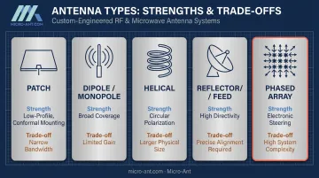
Choosing between them isn't a solo antenna-engineer decision. It requires tight coordination with platform engineers early, since an airborne blade antenna, a shipborne reflector, and a ground vehicle patch face entirely different mounting, weight, and exposure realities.
Environmental and Operational Factors
Humidity, temperature swings, vibration, and shock all distort how electromagnetic waves actually propagate once an antenna is installed. A design that performs beautifully in an anechoic chamber can behave very differently bolted to an airframe or ship hull, where nearby metal structures reshape the radiation pattern entirely.
RF matching circuits often get overlooked, yet they play a critical role here. Poor impedance matching between the antenna and transceiver wastes power, shrinks usable range, and caps data throughput. These problems surface in the field, not on the bench.
Critical Design Considerations for Defense & Aerospace Antenna Systems
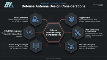
This is where general antenna theory meets the realities of military and aerospace deployment. Six factors dominate the conversation.
Size, Weight, and Power (SWaP) constraints hit airborne, satellite, and man-portable platforms hardest. Every gram and every watt is contested, forcing engineers to trade antenna gain against form factor rather than simply maximizing performance.
Ruggedization is the next non-negotiable. Fielded antennas need to survive a harsh set of environmental stresses:
- Shock and vibration from transport and platform operation
- Temperature cycling across extreme highs and lows
- Salt fog exposure in maritime and coastal environments
- Moisture ingress during prolonged field deployment
MIL-STD-810H is the standard most referenced here. Its actual scope is narrower than many assume: rather than a universal test checklist, it defines a tailoring process, meaning test severities should be derived from the platform's actual life cycle rather than borrowed wholesale from another program.
Multi-band and multi-constellation operation has become standard practice. Extended Ka-band designs, for instance, let a terminal roam across multiple satellite operators without a hardware change. Micro-Ant built this capability directly into its Ultra-Wide Band (3.5 GHz) Ka Antenna System, which earned the Satcoms Innovation Group's "Most Innovative" award in 2022.
Anti-jam and anti-spoof protection for GNSS/GPS antennas deserves a clear-eyed view. GPS.gov's guidance on protected PNT describes it as a layered defense:
- CRPA processing to null out jamming signals
- Multi-constellation and multi-frequency reception for redundancy
- Spoof detection and filtering algorithms
- Inertial aiding to bridge signal gaps
An antenna alone doesn't solve spoofing; it's one piece of a bigger stack.
Phased array challenges center on mutual coupling between densely packed elements, which can change active impedance and create blind angles across the scan sector. This has to be verified across frequency, temperature, and steering range, not just at boresight.
EMI/EMC compliance rounds things out. Multi-antenna platforms need equipment-level and platform-level EMC addressed separately (MIL-STD-461 and MIL-STD-464, respectively) to prevent one system's transmit chain from stepping on another's receiver.
The Antenna System Design & Development Process
A structured path from requirement to fielded hardware reduces risk at every stage. Five stages generally define this process:
- Requirements definition: Direct collaboration with program engineers and end users locks down mission profile, operating environment, and platform constraints. Skipping this step is the single most common cause of late-stage redesigns.
- EM simulation and modeling: Link budget analysis and propagation modeling predict performance before a single prototype gets built, saving cycles of costly rework.
- Bespoke prototyping: Rather than pulling from a catalog, engineering teams build and iterate custom hardware tailored to the mission profile. This is where 100% custom-engineered manufacturers differ from COTS suppliers.
- Validation and testing: In-house near-field chambers verify gain, pattern, and impedance on-site, skipping the wait for a third-party lab slot. Micro-Ant runs this scanning from 750 MHz to 40 GHz at its Jacksonville, FL facility.
- Manufacturing, documentation, and compliance sign-off: Final production runs alongside the traceability and quality records defense program audits require.
Why domestic, vertically integrated testing matters: consolidating design, prototyping, and validation under one roof keeps schedule risk contained across the entire program, not just the testing phase.
Types of Antennas Used in Defense & Aerospace Applications
Three categories cover most defense and aerospace RF needs:
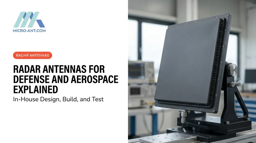
Phased array antennas steer their beam electronically instead of mechanically, critical for radar, electronic warfare, and beam-steerable SATCOM. NAVAIR's APG-79 AESA radar, for example, scans at speeds mechanical systems simply can't match, though the trade-off is calibration and thermal complexity across the array.
High-precision GNSS/GPS antennas support multi-constellation tracking for navigation and targeting systems where millimeter-level position accuracy isn't optional. These designs increasingly track multiple constellations simultaneously to maintain accuracy and resilience against interference.
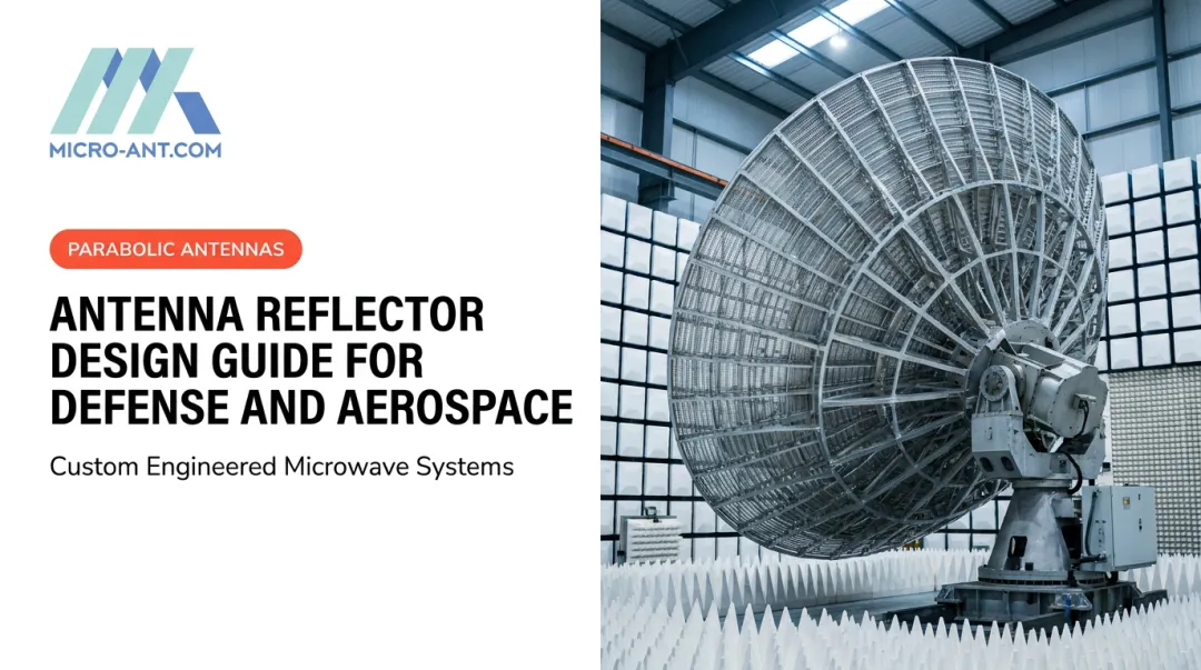
Reflector and feed systems remain the go-to for high-gain, wideband SATCOM links. Tri-band segmented designs, like Micro-Ant's Kore Composites "Veritas" line, consolidate multiple bands into a single reflector/feed assembly, saving weight and setup time for manpack and flyaway terminals.
Testing, Certification & Compliance Standards
Certifications and test data answer two different questions, and defense buyers should never conflate them.
AS9100:2016 and ISO 9001:2015 answer the first question: they certify that a supplier's quality management system meets aerospace-grade process discipline. They confirm how a company builds things — not the gain, pattern, or environmental rating of any specific antenna. Micro-Ant holds both certifications across its Jacksonville facility.
Environmental and RF performance testing answers the second question. This typically includes:
- Temperature cycling across the platform's expected operational range
- Vibration and shock testing tied to the mounting location
- Spherical or planar near-field antenna testing, commonly spanning 750 MHz to 40 GHz for wideband defense and SATCOM designs
Where that test data gets generated carries its own risk. Domestic testing infrastructure cuts a real risk out of defense programs: travel time, shipping delays, and scheduling backlogs common with overseas labs. For CAGE-coded, Made-in-USA suppliers like Micro-Ant (CAGE: 6XJFO), in-house testing means gain, pattern, and impedance data comes back in days, not weeks.

Frequently Asked Questions
What is the difference between COTS and custom/bespoke antenna design for defense applications?
COTS antennas offer speed and lower upfront cost since they are unmodified commercial products. Bespoke designs are engineered to exact mission, frequency, and environmental specs, delivering better field performance for demanding platforms.
What frequency bands are most commonly used in defense and aerospace antenna systems?
L, S, C, X, Ku, and Ka bands cover most defense and aerospace applications, from GNSS (L-band) to high-throughput SATCOM (Ka-band). Extended Ka-band designs let terminals roam across multiple satellite operators without swapping hardware.
What is a phased array antenna and why is it important for defense radar and SATCOM?
A phased array uses many elements with controlled phase and amplitude to steer its beam electronically instead of mechanically. This is critical for radar and SATCOM systems that must scan and track targets far faster than a rotating dish.
How long does it take to design and manufacture a custom antenna for a defense program?
Timelines vary with complexity, but most programs move through requirements definition, simulation, prototyping, and testing over several months. Complex phased array systems can take considerably longer given calibration and qualification demands.
What certifications should an antenna manufacturer have for defense contracts?
Look for AS9100:2016 and ISO 9001:2015 certification, plus an active CAGE code and current SAM.gov Unique Entity ID registration. These confirm both quality management discipline and legitimate standing as a federal supplier.
How do GNSS antennas ensure resistance to jamming and spoofing in contested environments?
No single feature solves this alone. Effective protection layers CRPA spatial processing, multi-constellation and multi-frequency tracking, precision filtering, and spoof detection together to maintain signal integrity under interference.