Search radar needs a wide azimuth sweep with a narrow vertical fan. Regional satellite downlink needs an elliptical footprint matched to a country's coastline, not a circle. Height-finding radar needs a beam shape no simple paraboloid can produce.
That's where shaped reflectors come in. Engineers deliberately modify the reflector's curvature, aperture outline, or feed system to produce a beam tailored to the mission rather than a generic symmetric one.
This guide covers how shaped reflectors work, the major design families, the parameters engineers must control, where these antennas get deployed, and how custom antenna houses like Micro-Ant turn these principles into hardware that ships.
Key Takeaways
- Shaped reflectors control azimuth and elevation beamwidth independently through curvature and aperture design
- Offset-fed, shaped dual-reflector designs cut blockage and push aperture efficiency above 70%
- Surface accuracy, feed illumination, and spillover control determine how closely hardware matches simulated patterns
- Applications include search radar, height-finding, satcom downlink, and rugged defense/maritime platforms
- Bespoke engineering, fabrication, and in-house testing shorten the path from design to fielded hardware
What Is a Shaped Reflector Antenna and How Does It Work?
A shaped reflector antenna is a reflector whose surface curvature or aperture outline has been intentionally altered, non-paraboloidal, asymmetric, or non-circular, to produce a radiation pattern matched to a specific job. Instead of the classic circular pencil beam, the output might be an elongated fan, an elliptical footprint, or a cosecant-squared pattern.
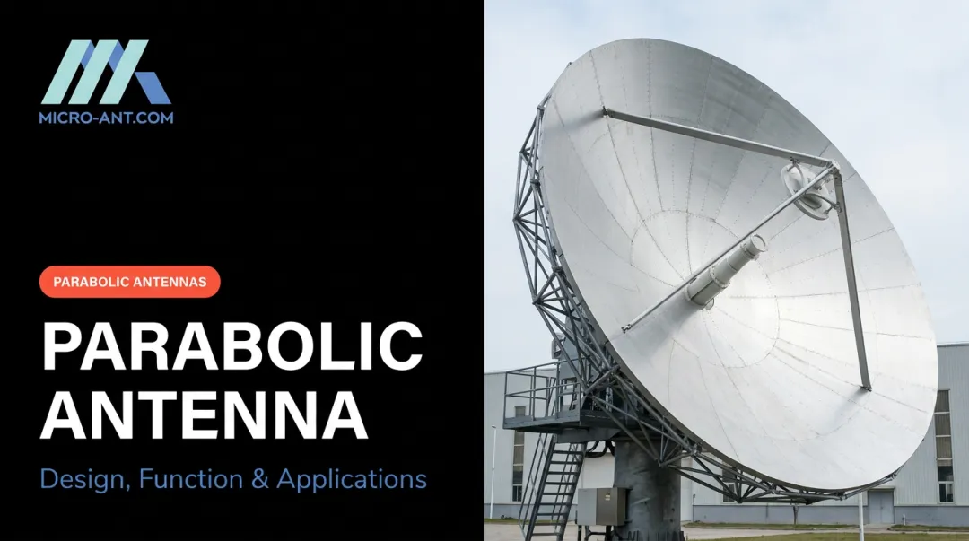
The base physics starts the same way for every reflector, shaped or not. A feed sits at (or near) the focal point and radiates a spherical wavefront. The reflector surface bends that wavefront into a collimated plane wave at the aperture.
Every path from the feed to the aperture plane must be equal in length, so the wave arrives in phase. That equal-path-length condition, straight from geometric optics, is what makes constructive interference and high directivity possible in the first place. Shaped designs still have to preserve this condition; they just route the rays differently to build a different aperture distribution.
That aperture distribution ultimately shapes the beam, and one rule governs all shaping work: widening the reflector in a given direction narrows the beam in that same direction. This aperture-beamwidth tradeoff lets engineers decouple azimuth and elevation beamwidth, widening the reflector along one axis while narrowing it along the other.
Feed illumination matters just as much as geometry. Two loss mechanisms show up constantly:
- Spillover: feed energy that misses the reflector edge entirely and never contributes to the beam
- Taper: uneven power distribution across the aperture, which lowers illumination efficiency even though it also suppresses nearby sidelobes
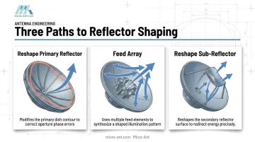
Shaped-reflector engineers manipulate both intentionally, achieving the shape through three routes: reworking the primary reflector surface, using an array of feeds, or reshaping a secondary sub-reflector in a dual-reflector system. Each approach opens a different design family, covered next.
Types of Shaped Reflector Antennas
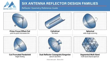
Prime-Focus vs. Offset-Fed Reflectors
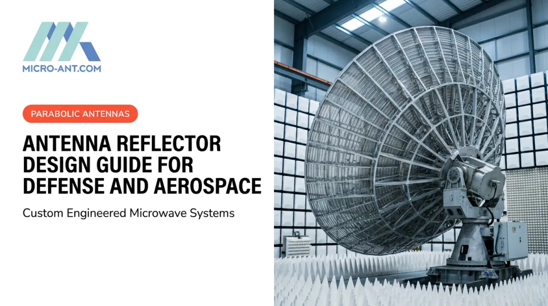
Prime-focus (axial) feed placement is the simplest architecture: the feed sits directly on the reflector's centerline. It's also the most compromised, because the feed and its support structure physically block part of the aperture.
NRAO's analysis of a 140-ft prime-focus telescope found aperture efficiency dropping from 75.04% without blockage to 65.94% with blockage included, a real illustration of what feed-structure shadowing costs. For a general paraboloid with -18 dB edge taper, NRAO cites 0.6 to 0.7 aperture efficiency as typical once illumination, spillover, phase error, and blockage are all accounted for (NRAO's 140-ft telescope analysis).
Offset-fed designs solve the blockage problem by using an asymmetrical section of a larger paraboloid, positioning the feed completely outside the beam path. The trade-off: IEEE research notes offset geometry increases manufacturing cost and makes feed alignment considerably harder. Offset reflectors often end up with an oval or egg-shaped rim, engineered so every edge point sees equal power density and the pattern doesn't distort.
Cylindrical and Spherical Reflectors
Cylindrical reflectors curve in only one direction. Instead of focusing to a point, they focus to a line, producing a fan-shaped beam that's narrow in the curved axis and wide in the flat one. IEEE research demonstrated fan-beam synthesis on a 3.65-meter, f/D 0.333 reflector operating at 13.6 GHz, confirming the technique holds up under physical-optics analysis. This geometry shows up frequently in radar and radio astronomy work.
Spherical reflectors take a different approach to a similar problem: wide-angle scanning without moving the reflector itself. The feed moves instead. NASA documentation notes the trade-off is spherical aberration, which requires corrective sub-reflectors or shaped optics to bring the output rays back to parallel.
"Orange-Peel" and Cut/Truncated Paraboloid Reflectors
Height-finder and search radar often need a narrow, elongated vertical fan beam. Engineers get there by trimming away the outer sections of a paraboloid that contribute least to the pattern, sections farthest from the feed.
What remains is a narrow, offset section of the parent paraboloid, sometimes described informally as "orange-peel" shaped because of its outline. The more precise engineering description is a cut or truncated paraboloid rotated 90 degrees, narrow in one dimension, built specifically to produce the fan beam height-finding equipment needs.
Dual-Reflector Shaped Systems (Cassegrain/Gregorian Shaping)
In Cassegrain and Gregorian configurations, engineers can reshape the sub-reflector itself rather than just the main dish. This redirects energy toward the outer main reflector more uniformly, improving illumination and gain.
NASA's shaped Cassegrain equations map a specified feed pattern into a more uniform aperture distribution while holding the optical path length condition. The payoff can be substantial:
- 84.5% aperture efficiency measured on a 1.5-meter offset dual-shaped reflector tested at 31.4 GHz (NASA's offset dual-shaped reflector study), one of the highest verified figures in the shaped-reflector literature
- 70-80% efficiency with -30 to -40 dB sidelobes targeted as a general design goal in a separate NASA study of shaped Cassegrain/Gregorian systems
The cost is real: more complex fabrication, tighter surface synthesis, and longer test cycles.
Segmented and Multi-Band Shaped Reflectors
Modern shaped-reflector work increasingly uses segmented panels that support multiple frequency bands from a single aperture. Micro-Ant's Veritas tri-band segmented reflector and feed system is one example, designed to serve several satcom bands without needing separate hardware for each. A published Ku/Ka reflector feed covering four separate bands from 12.25 GHz through 31.0 GHz achieved cross-polarization discrimination generally better than 30 dB, a good indicator of how demanding multi-band feed engineering gets.
Key Design Parameters for Shaped Reflector Engineering
Aperture Efficiency and the Beamwidth-Gain Trade-off
Aperture efficiency is the composite result of several loss mechanisms working together:
- Spillover loss (feed energy missing the reflector)
- Illumination taper (uneven aperture power distribution)
- Aperture blockage (feed and support structure)
- Surface shape errors (deviations from the ideal profile)
Shaped designs are engineered specifically to balance this trade-off for the target mission, not to maximize any single factor in isolation.
Beamwidth and gain move in opposite directions: the half-power beamwidth is roughly proportional to wavelength divided by aperture width. ITU-R gives the approximation θ₃ ≈ 70λ/D degrees when detailed antenna measurement data isn't available, with the constant varying depending on the actual aperture illumination distribution (ITU-R M.1851-1). A larger aperture relative to wavelength typically means a narrower beam and higher gain.
Surface Accuracy and the Ruze Relationship
Surface accuracy governs how much of that theoretical gain you actually get. NASA's work applies the Ruze relationship, where gain loss scales with the surface RMS error relative to wavelength.
Many shaped-reflector programs target a small fraction of a wavelength RMS accuracy as a design guideline, since even small deviations shift the phase at the focus and erode gain. The Ruze model assumes roughly random, Gaussian-distributed errors.
NASA found it can overpredict loss for structured deviations like those in membrane reflectors, so surface tolerance targets should be validated against the actual gain-loss budget for the mission rather than treated as a fixed universal number.
Frequency, Environmental, and Testing Considerations
Frequency band considerations get harder as bandwidth grows. Wideband or multi-band shaped reflectors, extended Ka-band designs especially, need more sophisticated feed and reflector engineering to hold phase accuracy and pattern integrity across a wider spectrum. A feed that performs well at one frequency can develop cross-polarization or pattern problems at the band edges if it wasn't designed for the full spread.
Mechanical and environmental ruggedization matters just as much as the RF design. Reflectors deployed on ships, aircraft, and field/defense platforms need to hold their shape accuracy through vibration, temperature swings, and moisture exposure. Testing regimes commonly reference MIL-STD-810 methods, covering vibration, shock, humidity, salt fog, and temperature cycling, tailored to the specific deployment environment rather than applied as one blanket sequence.
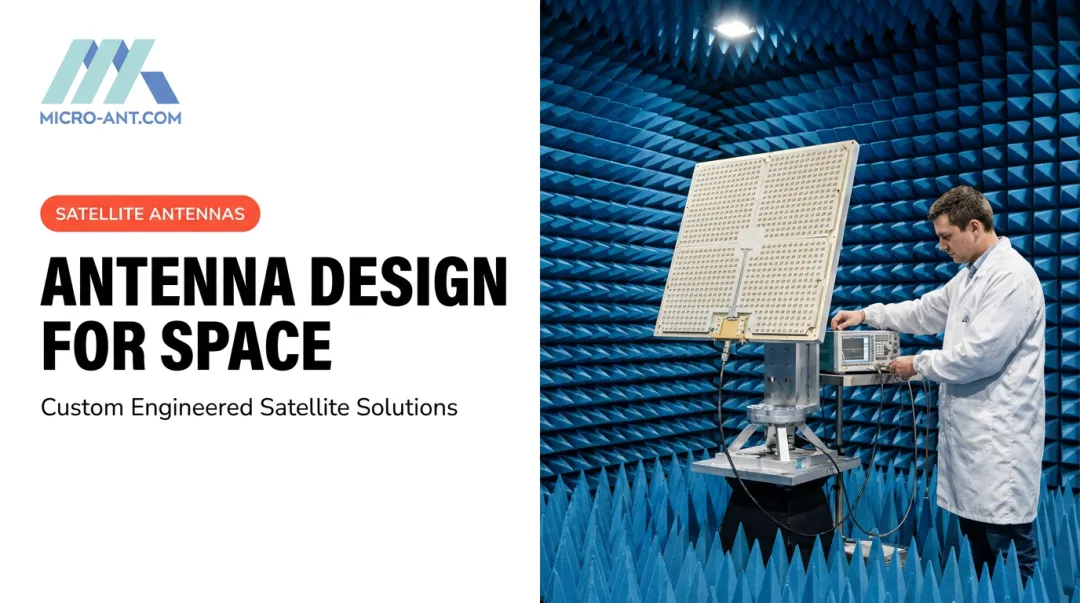
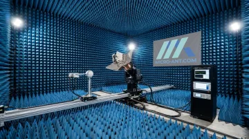
Validating all of this requires precision testing. Micro-Ant's in-house spherical and planar near-field chambers, covering 750 MHz to 40 GHz, let engineers verify gain, pattern, and efficiency before a shaped reflector ever leaves the Jacksonville facility.
Common Applications of Shaped Reflector Antennas
Radar systems rely on shaped beams to control azimuth and elevation coverage independently. Airport surveillance radar commonly uses cosecant-squared reflector shaping to maintain consistent detection across varying target altitudes and ranges. Height-finding radar uses the cut-paraboloid fan-beam approach described earlier to sweep a narrow vertical beam across the sky.
Beyond radar, satellite communications depend just as heavily on shaped and multi-band reflectors for regional downlink coverage. ITU-R documentation ties the resulting shaped-beam pattern to four engineering inputs: target coverage shape, minimum directivity requirements, normalized aperture size, and reflector scan aberrations. Shaped-reflector design must resolve all four simultaneously.
Radar and satellite systems typically operate in more controlled settings. Defense, aviation, and maritime platforms need rugged, shaped-beam antennas that hold their pattern integrity through:
- Constant vibration from vehicle or vessel motion
- Wide temperature swings between deployment environments
- Salt fog and humidity exposure on maritime platforms
- Repeated shock loading during transport and field use
Advantages and Design Challenges of Shaped Reflectors
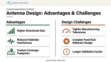
Shaped reflectors deliver real advantages over a standard symmetric dish:
- Higher directional gain through optimized aperture illumination
- Reduced sidelobe and backlobe interference, critical for radar target discrimination and satcom interference avoidance
- Custom coverage footprints matched to the actual mission, not a generic circular pattern
The challenges are just as real. Shaped-reflector projects demand:
- Tighter manufacturing tolerances to hold the surface accuracy the design calls for
- More complex feed and sub-reflector design, especially for dual-reflector or multi-band systems
- Longer design-validation cycles, since shaped patterns require more extensive near-field testing than a simple parabolic check
These trade-offs are why shaped-reflector programs benefit from a partner with in-house design, fabrication, and test capability under one roof. Micro-Ant's Jacksonville facility keeps all three functions together, rather than stitching together off-the-shelf components and hoping the integration holds.
Partnering with Micro-Ant for Custom Shaped Reflector Antenna Design
Micro-Ant has spent over 20 years designing and manufacturing bespoke antenna systems for defense, aviation, maritime, and satcom customers out of its Jacksonville, Florida facility. The company holds AS9100:2016 and ISO 9001:2015 certifications, standards that shape how design, fabrication, and testing get handled for every reflector that leaves the shop.
Two projects illustrate the shaped-reflector work in practice:
- Tri-Band Segmented Reflector and Feed ("Veritas") — segmented panel architecture built to support multiple satcom bands from a single aperture
- Ultra-Wide Band Ka Antenna System — which the Satcoms Innovation Group named Most Innovative, built for connectivity across extended Ka-band frequencies
Validating a shaped-reflector pattern before it ships matters as much as designing it correctly in the first place. Micro-Ant's in-house testing facility runs spherical and planar near-field chambers spanning 750 MHz to 40 GHz, covering L-band through Ka-band reflector, feed, and polarizer testing.
Customers verify gain, pattern, and efficiency domestically instead of shipping hardware overseas, cutting travel time and cost out of the validation cycle. A team of certified antenna design scientists, trained personally under founder Charles McCarrick, runs that testing program day to day.
Frequently Asked Questions
What are the different types of shaped reflector antennas?
The main categories are offset-fed, cylindrical, spherical, cut/truncated paraboloid, dual-reflector shaped systems (Cassegrain/Gregorian), and segmented multi-band reflectors. Each solves a different beam-shaping problem, from fan beams to regional satcom footprints.
How does a shaped reflector antenna work?
It modifies the reflector's curvature or aperture outline, or reshapes a sub-reflector, to control beamwidth independently in different directions. This produces an application-specific radiation pattern rather than a standard symmetric pencil beam.
What is the most efficient reflector antenna shape?
There's no single universal answer; efficiency depends on taper, spillover, blockage, and surface accuracy. Shaped offset dual-reflector designs have demonstrated some of the highest verified efficiencies, including an 84.5% measured result on a NASA test unit.
What is the difference between a parabolic and a shaped reflector antenna?
A standard parabolic reflector is a symmetric paraboloid producing a uniform pencil beam. A shaped reflector deliberately alters the curvature or outline to produce a beam pattern matched to a specific mission requirement.
What materials are used to manufacture shaped reflector antennas?
Common choices include aluminum, carbon-fiber composite panels, and metal mesh. Material choice affects weight, ruggedness, and how well the surface holds its accuracy under thermal and mechanical stress.
How is beam shape customized for applications like radar or satellite communications?
Engineers adjust reflector curvature, deploy feed arrays, or reshape a sub-reflector to map a known feed pattern into the desired footprint. This produces a fan beam for radar height-finding or a regional coverage shape for satcom downlink.