Introduction
As lower satellite bands approach capacity limits, spectrum engineers and system architects are looking higher. V-Band — spanning 40–75 GHz per IEEE Std 521-2002 — has moved from research interest to active procurement, with SpaceX, Boeing, OneWeb, and Telesat all holding FCC authorizations for V-Band NGSO constellations.
V-Band offers substantially more contiguous spectrum than Ka-Band, which spans just 13 GHz by comparison — a gap that matters when designing high-throughput systems competing for finite orbital resources. But wider spectrum comes with real engineering costs — oxygen absorption near 60 GHz, rain fade, power amplifier efficiency penalties, and precision manufacturing requirements that don't appear at lower frequencies.
This article breaks down what V-Band means in practice: its spectral boundaries, propagation physics, key technical properties, and the engineering constraints that govern link budgets, hardware selection, and system viability.
Key Takeaways
- V-Band spans 40–75 GHz (IEEE designation), placing it in the millimeter wave region with wavelengths of 4–7.5 mm
- Contiguous bandwidth far exceeds Ka-Band, supporting multi-gigabit satellite feeder links and backhaul
- The 60 GHz sub-band experiences ~15–16 dB/km oxygen absorption — a range limiter for terrestrial links, but a security asset for crosslinks
- Power amplifier efficiency runs 6.5–15% PAE, making thermal management a critical design constraint
- Tight mechanical tolerances at V-Band make purpose-engineered antenna solutions non-negotiable
What V-Band Frequencies Represent in Next-Generation Communications
IEEE Definition and Adjacent Band Boundaries
V-Band is formally defined by IEEE Std 521-2002 as the frequency range from 40 to 75 GHz. It sits within the ITU's Extremely High Frequency (EHF) classification, which covers 30–300 GHz. Adjacent bands are:
- Q-Band: commonly referenced in engineering literature as 33–50 GHz (though not formally designated in IEEE Std 521-2002)
- W-Band: 75–110 GHz per IEEE Std 521-2002
One persistent source of confusion: V-Band should not be conflated with UHF Band V (600–1,000 MHz), a completely separate designation used in broadcast and tactical radio contexts.
Why V-Band Matters Now
Ka-Band — 13 GHz wide under IEEE designation — is under increasing pressure from growing LEO constellations and terrestrial 5G deployments competing for the same allocations. V-Band's 35 GHz of total IEEE-defined spectrum provides room that Ka-Band simply cannot offer.
ITU WRC-19 Resolution 176 allocates 47.2–50.2 GHz and 50.4–51.4 GHz as Earth-to-space FSS bands, positioning V-Band as the uplink complement to Q-region downlinks in high-throughput satellite (HTS) architectures. Operators aren't studying V-Band — they're filing for it.
Regulatory Structure
In the U.S., two regulatory frameworks govern V-Band commercial use:
- Unlicensed (57–71 GHz): Governed by 47 CFR 15.255, amended in 2023. This covers WiGig-class short-range devices and 60 GHz fixed wireless links.
- Lightly licensed (71–76 GHz, 81–86 GHz, 92–95 GHz): Non-exclusive nationwide licenses with link registration under FCC Part 101, supporting multi-gigabit point-to-point links.
Which framework applies determines not just licensing obligations but antenna design requirements — gain, beamwidth, power limits, and interference mitigation all vary between commercial terrestrial deployments and satellite or defense systems operating under ITU and DoD frameworks.
The Frequency Range and Spectral Boundaries of V-Band
Nominal Operating Range and Sub-Band Characteristics
The full 40–75 GHz V-Band is not used uniformly. Different sub-bands serve distinct applications:
| Sub-Band | Primary Use | Key Characteristic |
|---|---|---|
| 47.2–50.2 GHz | Satellite FSS uplink (ITU WRC-19) | Primary gateway uplink allocation |
| 50.4–51.4 GHz | Satellite FSS uplink extension | Additional FSS uplink block |
| 57–71 GHz | Unlicensed short-range wireless (U.S.) | WiGig, fixed wireless access |
| ~60 GHz | Secure crosslinks, short-range | Oxygen absorption peak |
| 71–76 GHz | Lightly licensed point-to-point | Multi-gigabit backhaul |
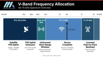
IEEE 802.11ad targets the 60 GHz band for multi-gigabit short-range links. IEEE 802.11ay (ratified 2021) covers license-exempt bands above 45 GHz, targeting throughput of at least 20 Gbit/s, more than triple 802.11ad's peak throughput.
V-Band's regulatory blocks include 14 GHz of unlicensed spectrum in 57–71 GHz and 3 GHz of FSS uplink in 47.2–50.2 GHz alone — contiguous allocations no single Ka-Band block matches.
Allowable Operating Margins and Boundary Conditions
V-Band link design cannot simply extrapolate Ka-Band margins. Two factors dominate:
Oxygen absorption: NTIA measurements show 16.31 dB/km attenuation at 60.7 GHz in dry air — about 50× the clear-air attenuation at 50 GHz (~0.3 dB/km). Systems near the 60 GHz peak must be designed for short-range or above-atmosphere operation.
Rain fade: ITU-R P.838-3 modeling shows rain-specific attenuation at horizontal polarization of approximately:
- At 50 GHz: 4.2 dB/km (10 mm/h), 8.9 dB/km (25 mm/h)
- At 60 GHz: 5.0 dB/km (10 mm/h), 10.1 dB/km (25 mm/h)
These are modeled values. Actual link budgets require local rain-rate data from ITU-R P.837 maps and specific availability targets before converting to fade margins.
For satellite feeder links where Q-region downlink and V-Band uplink are paired, adaptive coding and spatial diversity are standard fade mitigation techniques. Both must be specified at the antenna system level, not bolted on after the link budget is closed.
Key Technical Properties That Govern V-Band Performance
Atmospheric Propagation and Absorption
V-Band signals face two distinct attenuation mechanisms that interact differently by sub-band:
The oxygen absorption peak near 60 GHz (~15–16 dB/km) is the most operationally significant. It creates a natural propagation barrier that limits terrestrial range. For space-to-space crosslinks operating above the atmosphere, that absorption disappears entirely. This is precisely why the 60 GHz region is attractive for secure military satellite crosslinks: the same physics that limits ground-based range also limits ground-based interception.
At 47–52 GHz and 71–76 GHz, oxygen absorption drops substantially, making those windows more suitable for longer satellite feeder links where above-atmosphere propagation is needed over extended paths.
Beam Geometry and Antenna Gain
At V-Band wavelengths (4–7.5 mm), a given aperture produces a much narrower beam than at Ka-Band. This is beneficial: higher gain, better spatial isolation, inherent interference resistance. It also creates strict pointing requirements.
Angular misalignment that causes negligible gain loss at Ka-Band can produce significant degradation at V-Band. Thermal expansion in deployed structures, vibration during transit, and minor installation errors all become consequential. This is not a problem that scales linearly from lower-band experience.
Antenna designs for V-Band require purpose-engineered mechanical structures and feed alignment — not adapted Ka-Band hardware. Micro-Ant, whose AS9100:2016 and ISO 9001:2015 certified manufacturing processes emphasize precision fabrication, approaches this as a first-principles design problem: geometry, material selection, and feed alignment defined from scratch for the operating frequency.
Mechanical precision is only one dimension of V-Band system complexity. Power efficiency introduces a second, equally consequential constraint.
Device Efficiency and Thermal Load
Power amplifier efficiency at V-Band is substantially lower than at microwave frequencies. Published datasheets illustrate the scale of this gap:
- MACOM MAAP-011215-DIE (GaAs pHEMT, 55–70 GHz): 25 dBm output, 15% PAE
- Analog Devices ADPA7004 (GaAs pHEMT, 40–80 GHz): 28 dBm, 14% PAE
- GaN/SiC V-Band HPA (59–71 GHz): 40.3 dBm, 6.5% peak PAE
- Qorvo QPA0506 (GaN, 5–6 GHz C-band): 36.5 dBm, 53% PAE
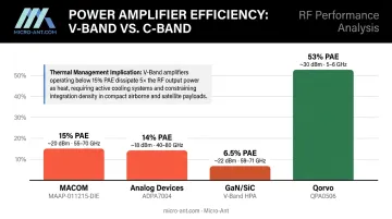
A C-band GaN amplifier converting power at 53% efficiency leaves little thermal waste. A V-Band module at 6.5% PAE turns most of its input power into heat. In compact satellite payloads or airborne systems, that thermal load requires heatsinking, thermal interface materials, and duty cycle limits built into the system architecture from the start — not addressed as an afterthought.
Component Interaction and Manufacturing Precision
At V-Band, the RF performance of a system is determined not just by individual component specifications, but by how every interconnect behaves at wavelengths of 4–7.5 mm.
Small dimensional errors in waveguide transitions, connector interfaces, or feed networks — errors that would be irrelevant at Ka-Band — can introduce measurable insertion loss, impedance mismatch, or spurious resonance at V-Band. Three requirements follow directly:
- Material selection must be evaluated at the sub-millimeter level
- Connector interface geometry requires tighter tolerances than lower-band equivalents
- Design validation in a controlled RF test environment is mandatory before field deployment
V-Band system performance is ultimately a manufacturing quality question, not just a component specification question.
V-Band Applications Across Next-Generation Communication Systems
Satellite Communications Feeder Links and Constellations
The clearest current application for V-Band is satellite gateway uplinks. ITU-R S.2461-0 explicitly discusses migrating very high throughput satellite (VHTS) feeder links from Ka-Band to Q/V-Band, freeing Ka-Band for user links — a practical architectural split driven by Ka-Band's bandwidth constraints.
ESA's ARTES 4.0 program has actively funded V-Band antenna development. The HTS Gateway Q/V-Band Feed Antenna activity, completed in 2022, designed Q/V gateway antennas scalable from 7 to 13 m aperture — reflecting the real engineering work underway for operational V-Band ground infrastructure.
The FCC constellation filings from SpaceX, Boeing, OneWeb, and Telesat confirm this is a production-planning band, not a research topic.
Secure Military and Defense Communications
V-Band's physical properties make it inherently resistant to interception and jamming — a combination few frequency bands can match:
- Narrow beam concentration: Energy is directed precisely, minimizing signal spread beyond the intended path
- Oxygen absorption attenuation: Any intercepted signal has already degraded substantially before reaching a ground-based receiver
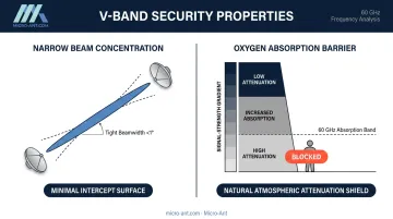
These properties have driven military satellite interest for decades. Defense requirements spanning tactical communications and missile guidance seekers continue to favor V-Band where signal security is non-negotiable.
Terrestrial Broadband and 5G Backhaul
Ericsson has documented that 60 GHz V-Band unlicensed links can support 1 Gbit/s over 1–2 km in street-level urban deployments — useful for small-cell backhaul where fiber isn't available. The oxygen absorption that limits range in this context also enables frequency reuse over short distances, improving spectral efficiency in dense deployments.
V-Band is also a candidate for satellite feeder/backhaul links supporting non-terrestrial network (NTN) architectures in 5G and emerging 6G systems. 3GPP standardization for V-Band NTN backhaul is advancing, making this an area to watch as 6G architecture decisions solidify over the next several years.
Engineering Challenges and Operating Constraints at V-Band
Atmospheric Attenuation and Link Budget Discipline
V-Band link budgets cannot be derived from Ka-Band experience with simple frequency-scaling adjustments. The 60 GHz oxygen absorption peak represents a discontinuity — a system designed for 50 GHz will behave very differently at 60 GHz even though the frequency difference is modest.
Rigorous link budget practice at V-Band requires:
- ITU-R P.676 gaseous attenuation models (not approximations)
- ITU-R P.838-3 rain fade coefficients with local rain-rate statistics
- Explicit fade margin allocation before finalizing EIRP and G/T requirements
- Clear identification of which sub-band the system will occupy, since attenuation varies significantly across V-Band's 35 GHz span
Precision Manufacturing and Mechanical Tolerances
At 4–7.5 mm wavelengths, mechanical precision directly determines RF performance. Sources of degradation in field-deployed systems include:
- Reflector surface error: Surface deviations that are negligible at Ka-Band introduce measurable gain loss at V-Band
- Feed alignment: Angular or lateral feed displacement reduces aperture efficiency
- Thermal expansion: Temperature cycling shifts physical dimensions, altering electrical performance
- Connector interfaces: Dimensional variability in connectors introduces insertion loss and return loss that accumulates through a system
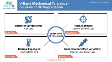
Manufacturers certified to AS9100 and ISO 9001 — Micro-Ant holds both — bring documented quality management processes that address these tolerance requirements systematically, not reactively.
Supply Chain and Testability
Those manufacturing precision constraints extend directly into procurement. The V-Band component ecosystem is less mature than Ka-Band:
- V-Band PA datasheets exist, but efficiency figures (6.5–15% PAE) require thermal engineering that Ka-Band designs often don't need at the same intensity
- Fewer COTS components are validated for reliable V-Band operation across the full temperature and vibration range required for defense or satellite applications
- Testing requires chambers capable of operating above 40 GHz; while NIST's Antenna Metrology Project supports near-field capability to 50–500 GHz and a configurable range up to 220 GHz, this infrastructure remains far less accessible than Ka-Band test facilities
- For U.S. unlicensed devices in the 57–71 GHz band, FCC measurement procedures under 47 CFR 15.255 apply to compliance testing
Given these gaps, procurement specifications should require device-level PAE data, module-level efficiency figures, duty cycle assumptions, and explicit thermal derating curves — not just output power specs.
Frequently Asked Questions
What is the frequency range of the V-Band?
V-Band spans 40–75 GHz per IEEE Std 521-2002, placing it firmly in the millimeter wave (mmWave) portion of the electromagnetic spectrum. Wavelengths range from approximately 4 mm at 75 GHz to 7.5 mm at 40 GHz.
What is the V-Band used for?
Primary applications span several domains:
- Satellite gateway uplinks (47.2–50.2 GHz FSS allocations)
- Unlicensed short-range gigabit wireless at 60 GHz
- Secure military crosslinks and multi-gigabit point-to-point backhaul
- V-Band feeder link infrastructure for next-generation satellite constellations
How secure is V-Band communication?
The 60 GHz sub-band's oxygen absorption (~15–16 dB/km) substantially attenuates signals before they reach ground-based receivers, limiting interception range. Combined with V-Band's narrow beam widths, this makes signals inherently difficult to intercept or jam — properties that have driven military satellite interest for years.
What is the difference between V-Band and Ka-Band?
Ka-Band (26–40 GHz) is the current dominant high-throughput satellite band, covering roughly 13 GHz. V-Band (40–75 GHz) offers 35 GHz of less congested spectrum but demands tighter engineering controls for atmospheric attenuation — making it Ka-Band's logical successor as capacity tightens.
What causes signal attenuation in V-Band frequencies?
Two mechanisms dominate: oxygen molecular absorption (peaking near 60 GHz at ~15–16 dB/km in dry air) and rain fade (modeled by ITU-R P.838-3). Both require explicit link budget accounting — neither is a minor correction at V-Band frequencies.