Introduction
The parabolic antenna is one of the most recognizable structures in modern communications — from a compact satellite dish on a rooftop to the 70-meter behemoths of NASA's Deep Space Network. That distinctive curved shape is not aesthetic. It is the mechanism. The geometry does the work.
Engineers and procurement specialists arrive at this topic with specific pressures. They need to know which reflector type fits their link budget, how feed configuration affects aperture efficiency, and what trade-offs to accept before committing to a design. Getting those decisions wrong means wasted gain margin, interference problems, or a dish that can't close the link.
What follows is a technical walkthrough: operating principle, component anatomy, feed configurations, key performance metrics, and applications spanning SATCOM, defense, GNSS, and deep-space systems.
Key Takeaways:
- Phase-coherent reflection focuses radiated energy into narrow, high-gain beams
- Gain scales with the square of aperture diameter: doubling dish size quadruples gain
- Feed configuration (prime-focus, offset, Cassegrain, Gregorian) directly determines aperture efficiency
- Applications range from VSAT terminals to 500-meter radio telescopes
- Parabolic designs suit long-range, point-to-point links — not area-coverage or wide-beam applications
How a Parabolic Antenna Works: The Core Principle
The Geometry That Drives Performance
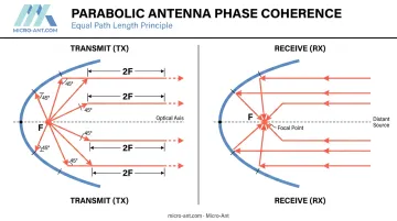
The parabolic antenna operates on a well-understood but geometrically precise principle: any ray emitted from the focal point of a paraboloidal surface reflects off the dish and travels parallel to the antenna's axis. Conversely, incoming parallel wavefronts from a distant source all reflect toward the same focal point. A flashlight reflector works the same way: the bulb sits at the focus, and the curved mirror redirects light into a forward-facing beam.
What makes this so effective is phase coherence. According to McMaster University's antenna lecture series, all ray paths from the focal point to the reflector surface and onward to the aperture plane are equal in total length — specifically 2F (twice the focal length). Because every path length is identical, all reflected wavefronts arrive in phase across the aperture. That phase alignment is what produces a tight, concentrated beam rather than scattered energy.
Transmit and Receive Signal Paths
The two operating directions are mirror images of each other:
Transmit mode:
- RF current travels from the transmitter via waveguide or coaxial cable to the feed antenna at the focal point
- The feed converts current into radio waves directed toward the reflector
- Waves bounce off the dish and emerge as a collimated, parallel beam
Receive mode:
- Incoming plane waves from a distant source strike the dish
- All reflected energy converges at the focal point
- The feed antenna collects this focused signal and passes it to the receiver
Why Directivity Is the Point
An omnidirectional antenna spreads power equally in all directions. A parabolic reflector concentrates nearly all radiated energy into a narrow pencil beam along its axis — yielding far higher signal strength in one direction without increasing transmitter power. This directivity is the primary reason parabolic antennas dominate long-range, point-to-point applications.
The reflector itself is a non-resonant structure. Changing the operating frequency requires only swapping the feed element at the focal point; the dish needs no modification. Some designs mount multiple feed elements simultaneously for multi-band operation — a practical benefit for ground stations that must support multiple satellite operators.
Anatomy of a Parabolic Antenna: Key Components
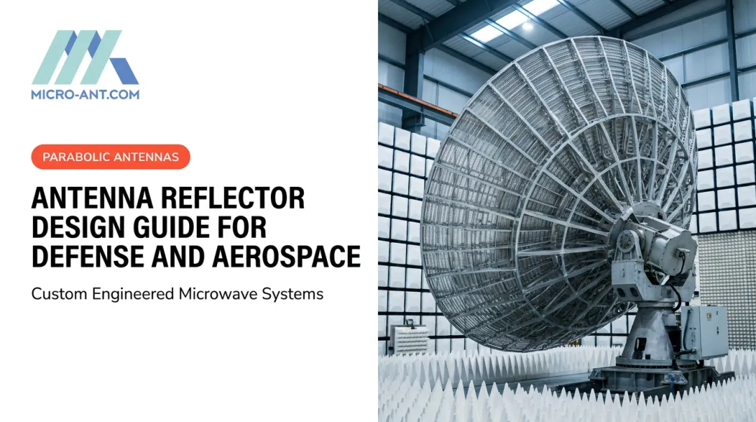
The Reflector Dish
The reflector is the large curved surface that redirects incoming or outgoing radio waves. Construction options include:
- Solid sheet metal — maximum reflectivity, but heavy and susceptible to wind loads
- Metal mesh — reflects radio waves as effectively as solid metal when mesh cell size stays at or below one-tenth of the operating wavelength, per NASA NTRS mesh-surface analysis. Dramatically reduces weight and wind resistance, making it the preferred choice for large outdoor installations
- Composite panels — common in portable and flyaway terminal designs where weight is critical
Per Ruze-type surface-loss analysis, RMS surface errors reduce realized gain — the reflector shape must be maintained to a tight tolerance relative to wavelength, and this requirement tightens as frequency increases. At Ka-band and above, even small deformations cause measurable gain loss.
Feed Antenna and LNB
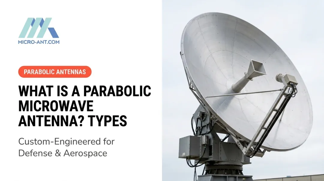
The feed antenna — most commonly a horn antenna or dipole — sits at the focal point and serves as the actual transducer. At microwave frequencies, a waveguide typically connects the feed to the transmitter or receiver.
In receive-only applications, a Low-Noise Block downconverter (LNB) mounts directly at the feed point, amplifying the received signal and converting it to a lower intermediate frequency for transmission via standard coaxial cable — avoiding significant signal loss over longer cable runs.
Feed Support and Aperture Blockage
In prime-focus designs, struts or a support boom hold the feed in the beam path directly in front of the dish. This structure physically blocks a portion of the reflected beam — reducing efficiency. That limitation drove the development of offset-feed and dual-reflector configurations.
Engineers sometimes add shrouds — cylindrical shields around the dish rim — in interference-sensitive environments to reduce sidelobes and back-lobe radiation.
Backing Structure and Pointing Mechanisms
Large dishes require a rigid truss or frame to maintain surface accuracy against multiple environmental stresses:
- Gravity loading — dish weight and orientation shift the surface profile across elevation angles
- Wind forces — dynamic loading deflects the structure, causing pointing error
- Thermal expansion — temperature swings across the dish introduce differential deformation
For satellite ground stations and defense applications, motorized azimuth/elevation mounts track moving satellites or targets. Allowable surface deformation tolerance is a critical engineering specification — mechanical pointing errors translate directly to gain loss given the narrow beamwidths involved.
Types of Parabolic Antennas
Classified by Reflector Shape
Paraboloidal (dish) antenna — The standard configuration: a full paraboloid of revolution with a circular rim, producing a narrow pencil beam along the axis. Used across satellite communications, radar, and point-to-point microwave links. Beam pattern narrows as aperture diameter increases relative to wavelength.
Cylindrical parabolic antenna — The reflector curves in one plane only, focusing energy along a line rather than a point. The resulting beam is fan-shaped — narrow in the curved dimension, wide in the other. Used in surveillance and search radar where wide azimuthal coverage with narrow elevation beams is needed.
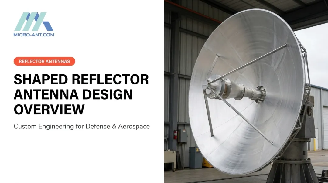
Shaped-beam antennas — Reflectors engineered with non-circular rims or different curvatures in horizontal and vertical planes to produce custom beam shapes. The cosecant-squared pattern used in air-traffic surveillance radar is one example; footprint-shaping designs covering specific geographic regions for broadcast satellites are another. Array-of-feeds configurations used on direct-broadcast satellites also fall in this category.
How the reflector is shaped determines the beam geometry. Feed placement determines how efficiently that reflector is illuminated — and the two choices interact directly.
Classified by Feed Configuration
| Configuration | Aperture Efficiency | Key Characteristic |
|---|---|---|
| Prime-focus (front feed) | ~55–60% | Simplest; feed blockage reduces efficiency |
| Offset-feed | ~70–80% | Feed outside beam path; standard in consumer VSAT |
| Cassegrain | ~65–70% | Convex subreflector; feed at dish vertex |
| Gregorian | >70% | Concave subreflector; feed behind primary focus |
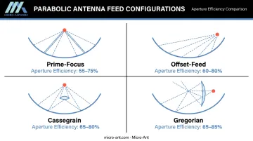
Prime-focus places the feed directly in front of the dish. Simple and common, but the feed and support struts block part of the reflected beam. Offset-feed variants move the feed to one side, eliminating blockage — the reason virtually all consumer satellite TV dishes use this configuration.
Cassegrain designs use a convex hyperboloidal secondary reflector near the focal point to redirect energy back to a feed mounted at or behind the primary dish vertex. This lets bulky feed assemblies or electronics sit at the dish center rather than suspended in front, a practical benefit for large ground stations and radar systems. Gregorian designs achieve similar results with a concave ellipsoidal subreflector positioned behind the primary focus.
When none of these standard configurations meet the frequency, gain, or environmental requirements of the application, fully custom designs take over. Micro-Ant's Tri-Band Segmented Reflectors and Ultra-Wide Band Ka Antenna System (recognized with the 2022 Innovation of the Year Award) are examples of purpose-built designs where reflector geometry, feed placement, and frequency coverage are engineered together from first principles.
Key Performance Metrics: Gain, Beamwidth, and Aperture Efficiency
Antenna Gain
Gain (G) measures how much power the antenna delivers in its peak direction compared to a hypothetical isotropic radiator. For a parabolic antenna, the ITU-R S.2196 formula gives:
G = 10 log₁₀ [η × π² × (D/λ)²]
where η is aperture efficiency, D is dish diameter, and λ is wavelength.
Gain scales with the square of aperture diameter — doubling the dish quadruples the gain. Across common configurations, that relationship produces a wide spread of values:
| Dish / Frequency | Aperture Efficiency | Gain |
|---|---|---|
| 2 m dish at 4 GHz | 0.55–0.70 | 35.9–36.9 dBi |
| 2 m dish at 6 GHz | 0.55–0.70 | 39.4–40.4 dBi |
| 25 m dish at 8.4 GHz | 0.50–0.70 | 63.8–65.3 dBi |
Beamwidth
Half-power beamwidth (HPBW) follows the approximation:
θ ≈ 70λ/D (degrees)
Gain and beamwidth are inversely related — a higher-gain antenna always produces a narrower beam. A 2-meter dish at 4 GHz yields roughly 2.6° beamwidth; at 6 GHz, that narrows to 1.75°. This precision enables frequency reuse between adjacent links, but it demands accurate mechanical alignment and active tracking for moving targets.
Aperture Efficiency
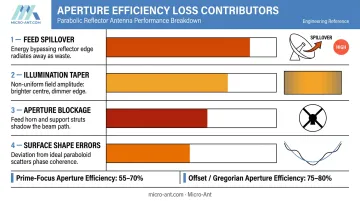
Aperture efficiency (η) quantifies how effectively the physical aperture is converted into radiated gain, expressed as a ratio from 0 to 1. It accounts for every loss mechanism that reduces realized gain below the theoretical maximum. The primary contributors are:
- Feed spillover : radiated energy that bypasses the reflector edge entirely
- Illumination taper : uneven power distribution across the aperture, with edges receiving less than the center
- Aperture blockage : the feed assembly and support struts intercept a portion of the reflected energy
- Surface shape errors : manufacturing or thermal deviations from the ideal paraboloid profile
Front-fed prime-focus designs typically achieve η = 0.55–0.70. Offset and Gregorian configurations, which eliminate feed blockage, can reach 0.75–0.80. Surface accuracy requirements tighten considerably at higher frequencies — a deformation negligible at C-band can produce measurable gain loss at Ka-band.
Applications of Parabolic Antennas Across Industries
Satellite Communications
Parabolic antennas are the workhorses of satellite ground infrastructure. High gain is non-negotiable for closing link budgets with GEO satellites at 35,786 km altitude. The VSAT market alone reached $14.14 billion in 2025, per MarketsandMarkets — reflecting the scale of parabolic antenna deployment for maritime, aviation, and enterprise connectivity.
Micro-Ant's antenna systems serve major operators including Intelsat, Inmarsat, Eutelsat, and SES O3B mPower MEO constellations — each with distinct certification, environmental, and RF compliance requirements that drive the engineering specification from the outset.
Defense and Radar
Parabolic reflectors are fundamental to military radar. The U.S. Navy's AN/SPS-49(V) — a long-range air-search radar with a parabolic reflector fed by an H-plane sectoral horn — provides automatic target detection and reporting within 250 nautical miles. Beyond radar, parabolic antennas appear in electronic warfare systems, secure point-to-point communications links, and intelligence-gathering installations where narrow-beam precision is essential.
GNSS Reference Stations and Precision Positioning
High-gain parabolic antennas support GNSS reference station infrastructure, providing the signal sensitivity and interference rejection needed for centimeter-level positioning. Industries that depend on this accuracy include:
- Precision agriculture and autonomous vehicle guidance
- Construction and mining site control
- Logistics and fleet management
Micro-Ant's high-precision GNSS antenna designs support multi-constellation reception — covering GPS, GLONASS, Galileo, and BeiDou — to maintain positioning accuracy across diverse operating environments.
Deep Space and Radio Astronomy
NASA's Deep Space Network operates three 70-meter antennas supporting L-, S-, and X-band reception for communication with spacecraft at extreme distances. Voyager 1, as of August 2024, was approximately 164.7 AU from Earth — and still communicating, thanks to the extraordinary gain achievable with large parabolic dishes.
At the scientific frontier, the Green Bank Telescope spans receivers from 100 MHz to 100 GHz, while China's FAST — a 500-meter active-surface telescope in Guizhou province — holds the distinction of being the world's largest single-dish radio telescope. Both push reflector geometry, surface tolerance, and feed design to the edge of what current manufacturing can achieve.

Microwave Point-to-Point and Backhaul Links
Parabolic dishes carry telephone, data, and television traffic across terrestrial microwave relay networks. Their narrow beams enable frequency reuse between adjacent links, making them spectrally efficient for cellular backhaul, enterprise WAN connections, and remote-site connectivity in oil and gas operations.
Advantages and Limitations of Parabolic Antennas
Parabolic antennas offer a distinct performance profile — strong where directional gain matters, constrained where flexibility or portability is the priority. Understanding both sides helps match the right antenna type to the mission.
Core Advantages
- Highest practical gain — large dishes routinely reach 40–50 dBi, outperforming any comparably sized deployable antenna
- Wide operating bandwidth — the non-resonant reflector supports feed replacement to change frequency without modifying the dish
- Weather resilience — metal reflectors maintain performance through rain, wind, and temperature extremes
- Versatility — effective from UHF through millimeter wave
Key Limitations
- Surface accuracy requirements tighten at higher frequencies; thermal and wind-induced deformation degrades performance in large dishes
- Aperture blockage in prime-focus designs reduces efficiency; offset or dual-reflector designs reduce blockage but add mechanical and alignment complexity
- Precise pointing required — small misalignment causes significant gain loss given narrow beamwidths; moving targets require active tracking
- Size and weight — large dishes require substantial support structures and are impractical where space or portability is constrained
Parabolic vs. Omnidirectional: When to Use Which
The decision comes down to link geometry and operational constraints:
| Factor | Parabolic | Omnidirectional |
|---|---|---|
| Gain & range | High — suited for long-distance links | Low — coverage over area, not distance |
| Direction | Fixed or trackable target required | All directions simultaneously |
| Interference rejection | Strong — narrow beam limits exposure | Weak — receives from all angles |
| Portability | Bulky; structures required for large dishes | Compact and lightweight |
| Best fit | SATCOM, radar, point-to-point backhaul | Mobile base stations, marine VHF, area broadcast |
Frequently Asked Questions
What is a parabolic antenna used for?
Parabolic antennas serve applications that demand high gain and narrow beam directionality: satellite communications ground stations, defense radar systems, point-to-point microwave links, GNSS reference stations, deep-space communications, and radio astronomy.
Which is better: parabolic antenna or omnidirectional?
Neither is universally better. Parabolic antennas excel at long-range, high-gain, point-to-point links with a known target direction. Omnidirectional antennas are preferred for broadcasting or receiving from all directions without beam steering. The application's geometry and coverage requirements determine the correct choice.
What frequencies do parabolic antennas use?
Parabolic antennas operate primarily at UHF and microwave frequencies (roughly 300 MHz and above), where wavelengths are short enough that practical dish sizes yield meaningful gain. Common bands include C-band (approximately 4–8 GHz), X-band (8–12 GHz), Ku-band (10–15 GHz), and Ka-band (17–31 GHz) for satellite and radar applications, with millimeter-wave designs used in specialized systems.
What is the difference between a Cassegrain and a prime-focus parabolic antenna?
A prime-focus antenna places the feed directly in front of the dish at the focal point — simple, but the feed and its supports block part of the reflected beam. A Cassegrain uses a secondary convex reflector near the focal point to redirect energy back to a feed mounted at the dish vertex, allowing bulky electronics to sit behind the dish rather than suspended in front of it.
What factors affect the gain of a parabolic antenna?
Three factors drive gain:
- Dish diameter — larger aperture produces higher gain
- Operating wavelength — shorter wavelengths yield higher gain for a given dish size
- Aperture efficiency — reduced by feed spillover, illumination taper, blockage, and surface errors
All three interact. A large dish with poor surface accuracy can underperform a smaller, well-built one.
Can a parabolic antenna transmit and receive at the same time?
Yes — parabolic antennas are bidirectional by design. Simultaneous two-way operation requires a duplexer or circulator to prevent the transmitter from saturating the receiver. Separate transmit and receive feeds on the same dish are another approach used in full-duplex systems.