Introduction
A satellite 22,000 miles away. A ship pitching through rough seas. A radar system tracking an incoming threat at the speed of sound. In each case, one thing determines whether the signal arrives clean or gets lost in the noise: antenna gain.
In satcom, defense, and deep-space communication, high-gain antenna design decides whether the mission works at all.
Here's the catch: many engineers assume more gain is automatically better. It isn't. Higher gain means a narrower beam, tighter tolerances, and less forgiveness for pointing errors.
This guide breaks down the fundamentals of gain, the core engineering trade-offs, and how to choose the right antenna type. It also covers why testing, drawn from Micro-Ant's decades of bespoke antenna engineering, is what separates a good design on paper from one that survives the field.
Key Takeaways
- High-gain antennas trade coverage area for a narrow, long-range beam
- Achieving high gain requires balancing aperture size, array configuration, feed precision, and bandwidth
- Parabolic, horn, helical, and phased array designs each solve different application problems
- Anechoic and near-field chamber testing confirms whether theoretical gain holds up in practice
Understanding Antenna Gain: The Foundation of High-Gain Design
Antenna gain measures how well an antenna concentrates radio energy in a specific direction compared to a theoretical isotropic radiator that spreads energy equally in all directions. It's expressed in dBi (decibels relative to isotropic).
The relationship is simple on paper:
Gain = Directivity × Efficiency
Gain vs. Directivity: Why They're Not the Same
Directivity describes the ideal, lossless concentration of radiated energy in a given direction. Gain accounts for what actually happens once you build the thing: resistive losses, impedance mismatches, and dielectric heating all eat into that theoretical number.
Gain will always be equal to or less than directivity, never more. Every real antenna pays an efficiency tax.
The Physics You Can't Engineer Around
Higher gain requires a physically or electrically larger aperture relative to the signal's wavelength. This is a hard diffraction-limited relationship, not a design preference:
G = 4π(Ae)/λ²
where Ae is effective aperture area and λ is wavelength. Per Balanis's foundational antenna theory work, narrow-beam directivity scales inversely with the product of the antenna's beamwidths, meaning tighter beams and bigger apertures go hand in hand. You can't shrink the beamwidth without growing the aperture or raising the frequency.
Is Higher Gain Always Better? No.
This is where the common misconception breaks down:
- Higher gain wins when: the signal path is fixed, distances are long, and line-of-sight is clean (satellite uplinks, point-to-point microwave, deep-space telemetry)
- Lower gain wins when: coverage must be broad, the platform is mobile, or pointing is unreliable (handheld radios, omnidirectional IoT nodes, vehicle-mounted comms)
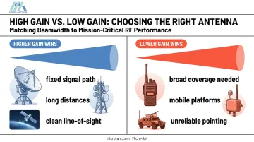
A narrower beam also improves signal-to-noise ratio by physically excluding off-axis interference — a critical advantage in defense and satcom links where jamming and multipath noise are constant threats.
Core Engineering Principles for Designing High-Gain Antennas
Every high-gain design decision comes back to one lever: gain scales with effective aperture relative to wavelength. Bigger apertures or higher operating frequencies both push gain upward. Everything else, from array architecture to reflector precision and materials, is a way of managing that relationship without blowing up size, weight, or cost.
Directivity increases directly with effective aperture area: double the aperture, and you meaningfully increase how tightly the antenna focuses energy. This is why deep-space dishes are enormous, and why compact terminals chase higher frequencies like Ka-band to squeeze more gain out of a smaller physical footprint.
Array and Phased Array Techniques
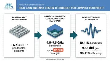
Combining multiple radiating elements with controlled phase relationships, a technique known as beamforming, multiplies effective gain and allows electronic beam steering without moving a single mechanical part.
- Doubling the number of transmit elements can raise EIRP by roughly 6 dB, according to Microwave Journal's guide to electronically steered antennas
- Scanning the beam 60 degrees off boresight introduces roughly 3 dB of scan loss
- Full digital beamforming lets systems form simultaneous beams while retaining gain per beam, with switching speeds measured in microseconds
This is the architecture behind modern radar tracking and multi-satellite communication systems. Steer electronically, skip the gimbal.
Reflector and Feed Optimization
Parabolic reflectors focus energy to a single feed point using precise curved geometry. The catch: surface accuracy matters enormously, and it gets harder as frequency increases.
Surface errors as small as a fraction of a wavelength can meaningfully degrade achievable gain. This is why higher-frequency reflector antennas (Ka-band and above) demand tighter manufacturing tolerances than their lower-frequency counterparts. There's simply less room for error relative to the wavelength being focused.
Advanced Materials and Structures
Engineered surfaces are changing what's possible in compact form factors. Artificial Magnetic Conductors (AMC) create an in-phase reflection layer that reduces destructive interference between direct and reflected fields.
A multilayer AMC design using five periodic patch layers demonstrated:
- 4.5–7.5 GHz operating bandwidth
- Average gain above 8 dBi
- Peak gain reaching 12 dBi
According to Microwave Journal's coverage of this wideband AMC antenna design, this approach boosts forward gain without enlarging a conventional reflector, which helps when size and weight budgets are fixed.
Managing the Bandwidth-Gain Trade-off
Single-frequency antennas typically hit higher peak gain than wideband designs. Squeeze more bandwidth out of a design, and you're usually trading away some peak performance.
Engineers narrow that gap through:
- Multilayer structures with air-gap coupling and stacked resonant layers
- Optimized patch geometries using floating or L-probe feed configurations
- Coupled resonances that widen impedance bandwidth without collapsing gain
One published prototype achieved 10.41% measured bandwidth with 9.63 dBi peak gain and 96.41% efficiency, proof that bandwidth and gain aren't mutually exclusive, just harder to optimize together.
Choosing the Right High-Gain Antenna Type for Your Application
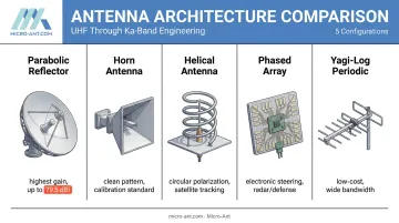
There's no universal "best" high-gain antenna. The right choice depends on frequency band, mounting environment, required beamwidth, and whether the platform is stationary or moving.
Parabolic Reflector Antennas
These use a curved dish to focus incoming or outgoing signals to a single feed point. They're the gain champions of the antenna world.
NASA's Deep Space Network illustrates just how far this scales: JPL reports gain up to 79.5 dBi for a 34-meter Ka-band uplink dish, with 70-meter X-band systems reaching 74.6 dBi. These numbers are band- and configuration-specific, not a blanket figure, but they show what's achievable when aperture size isn't constrained.
Horn Antennas
Horns deliver clean, predictable gain with excellent pattern purity, which is exactly why they're the go-to for calibration standards and point-to-point microwave links. Consistency, not extreme gain figures, is the priority.
Helical Antennas
Axial-mode helical antennas produce circular polarization with moderate-to-high directional gain, making them well-suited to satellite tracking terminals and mobile satcom applications where polarization mismatch would otherwise cause signal loss.
Phased Array Antennas
Phased arrays achieve high gain and electronic steering with zero mechanical movement. This makes them the standard choice for:
- Radar tracking systems
- Military communications requiring rapid beam redirection
- Multi-satellite tracking where dwell time on each target is limited
The trade-off is complexity — more RF chains, more calibration, and scan loss as the beam moves off boresight. Micro-Ant's phased array and beam-switching (ESA) antennas are engineered to manage that complexity for defense and satcom customers who need both speed and precision.
Yagi-Uda and Log-Periodic Antennas
These directional element arrays deliver moderate gain at low cost, which explains their long run in terrestrial applications like TV reception and short-range point-to-point links. Log-periodic variants add wide bandwidth, useful when a single design needs to cover multiple frequency ranges.
From Design to Real-World Performance: Applications and Testing
Mission-Critical Applications
Defense, satellite communications, maritime, and aviation sectors depend on high-gain antennas for connectivity that simply cannot fail. Micro-Ant's antenna testing and certification work supports satellite operators and defense customers whose certification reports need to hold up under FCC and MIL-STD scrutiny, not just simulation results.
That reliability starts with physics: range itself depends on more than gain alone. Free-space path loss follows the relationship:
Pr = Pt · Gt · Gr · (λ/4πR)²
In practice, range comes down to gain, transmit power, frequency, and line-of-sight clearance. That's why terrestrial microwave links reach tens of kilometers, while deep-space antennas maintain contact across billions of miles: same equation, different inputs.
Validating Gain Through Rigorous Testing
A simulated gain figure means nothing until it's measured. Environmental factors, manufacturing tolerances, and mounting conditions all shift real-world performance away from the model.
Micro-Ant validates every custom design in U.S.-based spherical and planar near-field test chambers spanning 750 MHz to 40 GHz, measuring:
- Full envelope radiation patterns
- Gain and efficiency
- Axial ratio and cross-polarization
- Performance across different ground-plane mounting conditions
For antennas headed into defense, maritime, or aviation service, environmental ruggedization testing matters just as much as RF performance. Salt fog, vibration, shock, and temperature extremes all get tested against MIL-STD environmental specifications before a design ships.
A dish that hits 79 dBi in a lab means nothing if it delaminates in a salt-spray environment six months later.
Frequently Asked Questions
Is a higher gain antenna better?
Only when the signal direction is known and long range is required. For mobile platforms or broad coverage needs, a lower-gain, wider-beamwidth antenna performs better and is more forgiving of pointing errors.
What type of antenna has the highest gain?
Large parabolic reflector antennas achieve the highest gain figures, with NASA's Deep Space Network dishes reaching up to 79.5 dBi in Ka-band configurations, according to published NASA DSN specifications. Gain always depends on the specific frequency and dish size involved.
How far can a high-gain antenna reach?
Range depends on gain, transmit power, frequency, and obstructions. Terrestrial point-to-point links typically cover tens of kilometers, while deep-space antennas maintain contact across billions of miles.
What is considered a good gain for an antenna in dBi?
"Good" gain is entirely application-dependent. Terrestrial and IoT links often work well in the single digits to low double digits, while satellite and deep-space systems require dish gains in the 50-80 dBi range.
How can you increase antenna gain without increasing its physical size?
Phased array beamforming, artificial magnetic conductor (AMC) ground planes, and higher-frequency operation all boost gain within a compact footprint. Each approach trades off differently in complexity, bandwidth, or manufacturing tolerance.
What is the difference between antenna gain and antenna directivity?
Directivity measures theoretical directional concentration with no losses factored in. Gain multiplies directivity by radiation efficiency, so gain is always equal to or lower than directivity.