Introduction
A SATCOM terminal loses lock mid-mission. An airborne radar can't resolve a target at range. Nine times out of ten, the reflector—not the electronics—causes the failure.
Engineers specifying custom reflectors face a tough balancing act: gain, weight, ruggedization, and frequency coverage all pull in different directions. A commercial dish that performs fine on a rooftop often fails the moment it hits shock, vibration, or salt fog in the field.
This guide breaks down the reflector types used in defense and aerospace programs, along with the design parameters that actually move the needle on performance. It also covers what to look for in a manufacturing partner capable of delivering mission-ready hardware on schedule.
Key Takeaways
- Reflector antennas pair a passive surface (parabolic, Cassegrain, segmented) with an active feed to form a high-gain beam
- Material choice, surface accuracy, and environmental ruggedization separate commercial reflectors from defense-grade hardware
- Wide-band and multi-band designs let terminals roam across satellite operators without swapping hardware
- Working with an AS9100/ISO-certified manufacturer with in-house testing cuts program risk and schedule delays
What Is an Antenna Reflector?
A reflector antenna consists of a passive reflecting surface (parabolic, hyperbolic, spherical, or ellipsoid) combined with an active feed element that transmits or receives the signal. The reflector itself does no amplification or processing. It just redirects electromagnetic energy.
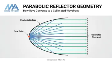
The parabola is the workhorse geometry for a reason. Every ray originating from the focal point reflects off the curved surface parallel to the antenna's axis, producing a collimated, in-phase wavefront. That physics is what lets a modest feed illuminate a large aperture and turn diffuse energy into a narrow, high-gain beam.
Why Reflectors Dominate High-Frequency Links
Reflector geometries are the standard choice once you move into higher microwave bands, where wavelengths shrink and directional gain becomes achievable with a reasonably sized aperture. Published program data illustrates the range:
| Program | Aperture/Band | Measured Gain |
|---|---|---|
| Seasat-A radar altimeter | 1 m | 40.5 dBi |
| TOPEX | 1.5 m, Ku/C | 43.3 dBi (Ku) |
| CPI 1188 deployable terminal | 1.8 m, C/X/Ku | 35.7-44.2 dBi |
These figures come from documented spacecraft and ground-terminal programs, not a blanket industry average. JHU APL's reflector antenna research confirms the underlying mechanism: equal electrical path lengths from focus to aperture produce the planar wavefront that makes this gain possible.
That same precision distinction trips up plenty of procurement teams, who often use "reflector" and "antenna" interchangeably. They're not the same thing: the reflector is just the passive surface, while the complete antenna system includes the feed, the reflector, and the support structure that keeps everything aligned under load.
Types of Reflector Antennas for Defense & Aerospace
Reflector geometry gets chosen based on mission profile, platform size, and frequency requirements. There's no single "best" design, only the right trade-off for the application.
Prime Focus Parabolic Reflectors
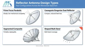
The prime focus design is the simplest configuration: a single paraboloid with the feed mounted directly at the focal point. The f/D ratio (focal length divided by aperture diameter) drives feed illumination and spillover loss.
No universal f/D standard exists. A Microwave Journal-documented prime-focus design at f/D = 0.392 achieved 35 dB gain at 18.5 GHz with 71.3% efficiency, while CPI's rugged deployable reflector runs at f/D = 0.6.
Program requirements, not a fixed rule, determine the right ratio. This design remains common on fixed ground terminals and large-dish radar where a single reflector keeps mechanical complexity low.
Cassegrain & Gregorian Dual-Reflector Systems
Dual-reflector systems add a sub-reflector between the feed and the main dish. In a Cassegrain configuration, that's a hyperbolic sub-reflector paired with a parabolic main reflector, a geometry confirmed in JPL's Deep Space Network documentation.
The benefit: shorter feed lines and reduced loss between the feed electronics and the aperture. That matters most where space and weight are tight:
- Shipboard SATCOM terminals with limited deck space
- Aircraft-mounted radar and comms arrays
- Satellite payloads where every kilogram counts
Efficiency gains from dual-reflector optics are configuration-specific rather than universal. NASA-documented modifications to shaped subreflectors have delivered 10-20% efficiency improvements over conventional designs in specific large-aperture systems.
Segmented & Composite Reflectors
For man-portable terminals and satellites where a single rigid dish won't fit in the transport case or launch shroud, segmented and composite panel designs solve the packaging problem. Panels fold, stack, or unfurl on deployment, then lock into a precise parabolic shape. Field crews assemble these systems without specialized tools, a requirement that manpack and flyaway missions demand.
Micro-Ant's Kore Composites division builds exactly this kind of hardware. The Veritas Tri-Band Segmented Reflector, launched at the SOFI Conference in 2022, was engineered around the reality that flyaway and manpack terminals need reflector performance without the bulk of a one-piece dish.
Shaped & Multi-Band Reflectors
Shaped reflectors modify the surface contour (rather than a pure paraboloid) to redistribute gain across a specific coverage footprint. This is common on satellite payloads targeting an irregular geographic beam rather than a simple circular spot.
Multi-band designs go a step further, supporting several frequency bands from one aperture. A single Ku/Ka aperture eliminates the added weight and cost of carrying separate reflectors for each band.
This is where Ka-band roaming matters most for defense. A wideband terminal can hop between satellite operators without a hardware swap, a capability documented in Cobham's reflector-based Ku/Ka terminal supporting multi-orbit operation.
Critical Design Parameters for Mission-Critical Reflectors
Five variables consistently separate a reflector that survives deployment from one that fails in the field.
Material Selection
| Material | Strengths | Trade-offs |
|---|---|---|
| Aluminum | Cost-effective, well understood, easy to machine | Heavier than composites; less thermally stable |
| Carbon fiber composite | Low mass, low thermal expansion | Moisture absorption and creep need engineering around |
| Compression-molded SMC | Corrosion resistance, stiffness, wind-load performance | Tooling cost for custom geometries |
Carbon-fiber composites are typically chosen for spacecraft reflectors to minimize mass and thermal expansion, though moisture absorption and nonlinear thermal behavior require careful design. There's no universal "best" material. It depends on the platform's weight budget, thermal environment, and expected service life.
Surface Accuracy and the Ruze Relationship
Surface accuracy becomes exponentially more critical as frequency climbs. The governing relationship, documented in NASA's Ruze equation research, shows directivity loss growing as RMS surface error increases relative to wavelength.
What this means in practice: a surface tolerance that's perfectly acceptable at S-band can devastate gain at Ka-band. There's no generic tolerance spec that transfers across bands. Every aperture and frequency combination needs its own error budget calculated against the actual wavelength in use.
Environmental Ruggedization
Defense-grade reflectors get qualified against MIL-STD-810H, the active DoD standard for environmental engineering testing. Relevant methods include:
- 501.7/502.7 – High and low temperature extremes
- 509.7 – Salt fog resistance for maritime and coastal platforms
- 514.8 – Vibration testing
- 516.8 – Shock testing
MIL-STD-810H functions as a tailoring framework for environmental qualification. The specific methods and severity levels get selected based on the platform's actual operating environment.
Frequency Band and Bandwidth
Defense programs increasingly want ultra-wideband reflectors that roam across multiple satellite constellations without a hardware change. This drives demand for reflector-feed combinations engineered around wide instantaneous bandwidth rather than a single narrow channel. Micro-Ant's Ultra-Wide Band Ka antenna system, which spans 3.5 GHz of instantaneous bandwidth and earned a 2022 SatCom Technology of the Year award, shows what that approach looks like in a fielded design.
Testing and Validation
Near-field chamber testing verifies gain and far-field pattern performance before hardware ever reaches the field. Micro-Ant runs two chamber configurations in-house at its Jacksonville facility:
- Spherical near-field chamber covering 750 MHz to 40 GHz, for full 360° pattern certification
- Planar near-field chamber for fast production and design-verification testing
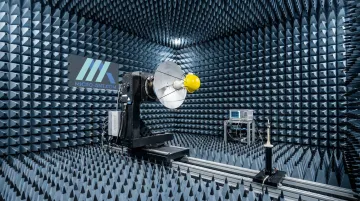
Domestic, in-house testing removes the schedule risk of shipping hardware to third-party labs and waiting weeks for results.
Advantages of Reflector Antennas in Defense & Aerospace
Reflector antennas earn their place on mission-critical platforms for several concrete engineering reasons:
- High gain, narrow beamwidth – Extends usable range for long-range, low-power satellite links and radar, where every dB of gain counts
- Design flexibility – Feed placement and reflector shaping adjust beamwidth without redesigning the entire system, supporting multiple mission profiles from one platform architecture
- Better link margins – Improved directivity reduces power wastage, a meaningful advantage for power-constrained platforms like UAVs and small satellites, where Micro-Ant's composite reflector designs help squeeze extra range from every watt
According to a NASA technical report on mobile satellite systems, larger, higher-gain spacecraft antennas reduce the gain and power required on the ground side of the link.
That trade-off runs both directions, and it is why reflector geometry gets so much engineering attention on power-limited platforms.
Choosing the Right Reflector Antenna Design & Manufacturing Partner
Not every antenna shop can deliver defense-grade reflector hardware. Three things separate a capable partner from a risky one: certifications that prove process discipline, in-house design-through-test capability, and a track record with demanding programs.
Certifications that actually matter:
- AS9100:2016 – Aerospace-specific quality management requirements covering risk, traceability, and counterfeit-part prevention
- ISO 9001:2015 – The base quality management standard AS9100 builds on
Neither certification proves RF performance on its own. What they demonstrate is a documented, audited process for consistently meeting drawing specifications, which matters enormously when a reflector has to perform identically across a production run of dozens or hundreds of units.
In-house design-through-test capability compresses program timelines. When engineering, prototyping, and chamber testing all happen under one roof, there's no shipping hardware between vendors and no waiting on third-party lab schedules.
Proven track record. That history matters as much as certifications. Micro-Ant has built its Jacksonville, Florida operation around this model for more than 20 years, holding both AS9100:2016 and ISO 9001:2015 certifications.
Its engineering team developed the Ultra-Wide Band Ka Antenna System, recognized as SatCom Technology of the Year in 2022, to solve the multi-operator roaming challenge defense and government SATCOM programs increasingly demand.
The customer roster reflects that track record: satellite operators and defense organizations including Iridium, Intelsat, and ARSTRAT rely on Micro-Ant hardware.

Frequently Asked Questions
What is a reflector antenna?
A reflector antenna is a passive reflecting surface, typically parabolic, paired with an active feed element. Together they redirect electromagnetic energy to achieve high gain and tight directivity.
What are the advantages of a reflector antenna?
Reflector antennas deliver high gain and narrow beamwidth for long-range links, plus design flexibility through feed placement and surface shaping. This translates into reduced power waste and versatility across satellite, radar, and telemetry applications.
What materials are used in defense-grade antenna reflectors?
Aluminum, carbon fiber composites, and molded composite substrates are the primary options. Aluminum offers cost efficiency, while composites reduce weight and improve thermal stability at a higher tooling cost.
How does a parabolic reflector improve antenna gain?
The parabola's geometry ensures every ray from the focal point travels an equal path length to the aperture, producing a collimated wavefront. That collimation concentrates scattered energy into one narrow, high-gain beam.
What certifications should a reflector antenna manufacturer have for defense contracts?
AS9100:2016 and ISO 9001:2015, the certifications Micro-Ant holds, are the key quality benchmarks defense and aerospace primes look for. They certify the manufacturer's quality management system, not the antenna's RF performance directly.
Can reflector antennas be customized for specific frequency bands?
Yes. Bespoke reflector and feed design allows tuning for single-band, multi-band, or ultra-wideband operation depending on the mission's satellite operators and frequency requirements.