Many people use "RF design" and "RF integration" as if they mean the same thing. They don't. Design and integration are separate disciplines that happen to depend on each other completely.
This guide breaks down both terms, walks through the process from concept to deployment, covers the hardware involved, and looks at the challenges that trip up even experienced teams. Along the way, we'll show how bespoke engineering partners like Micro-Ant apply these principles for defense, aviation, and maritime clients who can't afford connectivity failures.
Key Takeaways
- RF design creates the components and blueprints; RF integration turns them into a working system.
- Simulation tools can cut satellite antenna development time by roughly 5x, per Dassault Systèmes research.
- Poor radome or cable integration can degrade radar and GNSS performance even with a sound antenna design.
- Environmental durability and spectrum congestion remain the two toughest challenges in fielded RF systems.
- In-house testing and domestic manufacturing shorten certification timelines and reduce client travel costs.
What Is RF Design? Understanding the Basic Concept
RF design is the engineering discipline focused on building circuits, components, and systems that transmit and receive electromagnetic energy across the radio frequency spectrum, roughly 30 kHz to 300 GHz. The goal is straightforward to state and hard to achieve: maximize signal integrity while minimizing interference, loss, and noise.
The Building Blocks of RF Design
RF designers juggle several interlocking variables:
- Frequency planning - selecting and allocating spectrum bands to avoid overlap and interference
- Impedance matching - ensuring signal energy transfers efficiently between components instead of reflecting back
- Gain and noise figure optimization - amplifying the wanted signal while suppressing unwanted noise
- Filtering - blocking out-of-band signals that would otherwise corrupt the desired transmission
Get any one of these wrong, and the whole chain suffers. A perfectly filtered signal still fails if impedance mismatches send half the power bouncing back toward the source.
Chip-Scale vs. Platform-Scale Design
RF design spans two distinct scales. At the chip level, engineers work with RF integrated circuits, tiny silicon dies combining amplifiers, filters, mixers, and oscillators. At the systems level, the focus shifts to antennas, subsystems, and platform-wide engineering, the domain where companies like Micro-Ant concentrate their antenna engineering work.
Custom antenna engineering fits here, in the physical structures that radiate and capture RF energy across a platform, distinct from the chip-level circuitry itself.
RF design underpins nearly every connected system in defense, aviation, and maritime operations, including:
- Satellite communications terminals
- Radar systems
- GPS/GNSS navigation
- Tactical defense radios
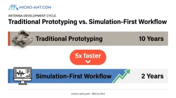
Modern RF design increasingly leans on electromagnetic simulation software rather than pure trial-and-error prototyping. ANYWAVES, a French satellite antenna developer, reports that simulation and related technologies help it deliver antenna products roughly 5 times faster than earlier methods.
The shift compressed development timelines from a decade down to about two years for new antenna technologies. ANYWAVES now uses CST Studio Suite daily to model electromagnetic interference before committing to physical hardware.
What Is RF Integration?
RF integration is the process of combining individually designed RF components, subsystems, and antennas into one functional system within a larger platform, whether that's a vehicle, vessel, aircraft, or network.
Here's the clean way to separate the two disciplines: Design creates the blueprint and the parts. Integration makes those parts work together as a single system in the real world.
What Successful Integration Actually Requires
Integration success hinges on details that never show up on a datasheet:
- Impedance matching across interconnects - not just within a component, but across every connector and cable joint
- Minimizing insertion loss - every cable run and connector costs signal strength
- Managing thermal and mechanical constraints - vibration, heat, and structural stress on a moving platform
- Ensuring EMI/EMC compliance - preventing the system from interfering with itself or nearby equipment
Consider a satcom antenna terminal mounted on a moving vehicle or vessel. The antenna itself might perform flawlessly on a test bench. But mounting position, cable routing, and radome material all affect whether that same antenna performs in the field. Get the radome wrong, and you've built a great antenna inside a bad system.
When Integration Fails Even Though Design Didn't
Integration failures are common, and they're often mistaken for design flaws. A 1995 FAA operational test offers a clear example: after installing a new Fixed Ground Antenna Radome at a radar facility in Trinidad, radar reinforcement performance over the 50 to 105 nautical mile range dropped from 70% to 60%.
Coverage plots measured 1,000 to 2,000 feet worse than before installation. At a separate site, azimuth performance for two tracking systems degraded by roughly 8% to 9% purely from the radome swap.
The antenna design hadn't changed. The integration had, and performance paid the price.
Key Components Involved in RF Design and Integration
Both disciplines rely on a shared set of hardware building blocks:
- Antennas - the interface between the system and free space
- Amplifiers (LNA/PA) - low-noise amplifiers boost weak received signals; power amplifiers strengthen outgoing transmissions
- Filters - remove unwanted frequencies from the signal chain
- Mixers and oscillators - shift signals between frequency bands
- RF cabling, connectors, and radomes - the physical infrastructure connecting everything, and protecting it from the elements
Beyond these core building blocks, compact multi-band systems increasingly rely on integrated passive devices and interposers. According to IEEE's Heterogeneous Integration Roadmap, interposers help optimize cost, performance, power, and size when connecting ICs, passive components, and the broader system.
This tradeoff matters most for space- and weight-constrained aerospace and mobile platforms, where every gram and cubic inch counts.
Component selection is never generic. It is driven by:
- Frequency band requirements specific to the mission
- Power output needs
- Environmental exposure demands, especially in defense and maritime settings where saltwater, vibration, and temperature extremes are constant
The RF Design and Integration Process: From Concept to Deployment
Taking an RF system from idea to fielded hardware follows a fairly consistent sequence, even though the details vary by application.
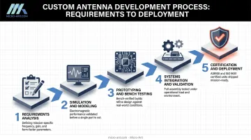
- Requirements analysis - defining frequency bands, gain targets, coverage area, and platform or environmental constraints before any design work starts
- Simulation and modeling - using EM simulation and circuit modeling tools to validate designs virtually before building anything physical
- Prototyping and bench testing - building initial hardware and testing signal performance, impedance matching, and radiation patterns
- Systems integration and validation - mounting components onto host platforms and testing for interference alongside environmental resilience, including temperature extremes, vibration, and humidity
- Certification and deployment - final validation against military or industry standards before the system goes live
Simulation Reduces Costly Rework
Skipping straight from concept to hardware is expensive. Simulation-first workflows let engineers catch electromagnetic interference issues, refine antenna shape, and validate performance digitally, minimizing the need for repeated physical prototypes. Once a design clears simulation and prototyping, it still has to pass formal certification before deployment. Certification against military or industry standards is often the longest pole in the tent.
In-house, domestic testing facilities with wide frequency-range chambers, like Micro-Ant's spherical and planar near-field chambers covering 750MHz to 40GHz, shorten this phase considerably. Instead of shipping hardware overseas or waiting in queue at third-party labs, projects can move through validation and back into production faster, with fewer logistics headaches.
Common Challenges in RF Design and Integration
Three challenges show up again and again across defense, aviation, maritime, and telecom projects.
Interference and Spectrum Congestion
The electromagnetic spectrum keeps getting more crowded. The FCC's 2024 order on non-geostationary satellite systems set inter-round protection criteria at 3% time-weighted average throughput degradation for long-term interference. That threshold shows how tightly shared frequency bands must now be managed across multiple satellite operators.
Environmental Durability
Defense, aviation, and maritime systems face conditions that would destroy consumer-grade electronics: extreme temperature swings, constant vibration, salt fog, and humidity. Standards like MIL-STD-810 and IEC 60945 exist precisely because these environments punish weak engineering.
Cost, Schedule, and Customization Risk
Off-the-shelf RF components rarely meet mission-specific requirements exactly. That gap drives demand for engineering partners like Micro-Ant, capable of bespoke design-to-manufacture work rather than catalog substitutions.
How Micro-Ant Delivers Bespoke RF Design and Integration Solutions
Micro-Ant has spent over 20 years designing and manufacturing bespoke antennas for defense, aviation, maritime, and land applications, backed by ISO 9001:2015 and AS9100:2016 certifications. That combination matters because it signals process discipline in industries where a failed antenna can jeopardize the mission itself.
A few examples of how this plays out in practice:
- Ultra-Wide Band (3.5 GHz) Ka Antenna System - built to support roaming across multiple satellite operators, solving the interoperability challenge that plagues fixed-band terminals
- High-precision GNSS antenna designs - engineered to support multiple satellite constellations for applications demanding tight positioning accuracy
- In-house testing facilities - spherical and planar near-field chambers spanning 750 MHz to 40 GHz, allowing performance validation without shipping hardware to third-party labs
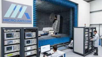
This capability carries real weight: testing turnaround can make or break program timelines. Keeping validation domestic and in-house cuts travel time and cost for clients, while still meeting the rigorous documentation standards that defense and satellite operator certifications demand.
Frequently Asked Questions
What is the basic concept of RF design?
RF design is the engineering process of creating components and systems that transmit and receive signals across the radio frequency spectrum. The focus is on signal integrity and minimizing interference.
What is an RF integrated circuit?
An RFIC is a chip-level circuit that combines amplifiers, filters, mixers, and oscillators onto a single silicon die. This enables compact, high-frequency signal processing in a small footprint.
What is the difference between RF design and RF integration?
Design creates the technical blueprint and individual components. Integration assembles and validates those pieces into one working system on a host platform like a vehicle, vessel, or aircraft.
Why is testing critical to RF design and integration?
Testing validates signal performance, interference resistance, and environmental durability before a system is fielded. Skipping it risks costly failures in mission-critical deployments.
What industries depend most on RF design and integration?
Defense, satellite communications, aviation, maritime, and telecom sectors rely heavily on precise RF design and integration. All of them need reliable connectivity in demanding, often harsh operating environments.
How long does a typical RF antenna integration project take?
Timelines vary based on complexity, platform, and certification requirements. In-house testing and domestic manufacturing, like Micro-Ant's Jacksonville facilities, can shorten integration and validation cycles.