
Online tutorials make it look easy: bend some wire, mount it on a plate, plug in a receiver. Real-world results tell a different story. Two builders can follow the same instructions and get wildly different signal quality, depending on polarization, tuning accuracy, and gain choices.
This guide walks through the actual build steps, the parameters that separate a working antenna from a dead one, the mistakes that trip up most first-time builders, and the point at which a DIY antenna stops being good enough.
Key Takeaways
- L-band spans roughly 1-2 GHz, covering GNSS, Inmarsat, Iridium, and weather satellite downlinks
- Helix antennas deliver higher gain for voice-channel decoding than simpler patch designs
- Right-hand circular polarization, VNA-verified tuning, and low-loss coax determine build success
- LNA placement matters as much as antenna design, since it sets your system's noise floor
- DIY builds suit hobbyist reception and prototyping, not regulated or mission-critical programs
How to Build an L-Band Satellite Antenna: Step-by-Step
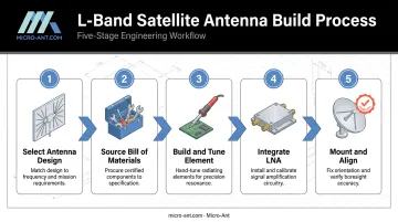
Building an L-band antenna involves five stages: choosing a design, gathering parts, building and tuning the element, adding a low-noise amplifier, and mounting it correctly. Skip a step, and you'll spend hours troubleshooting a "dead" antenna that was never tuned properly in the first place.
Step 1: Select Your Antenna Type and Design Approach
Two designs dominate DIY L-band builds:
- Patch antennas: flat, compact, and relatively easy to fabricate on a PCB or copper-clad board. Lower gain, but forgiving for basic GNSS or data reception.
- Helix antennas: wound copper elements over a ground plane that deliver noticeably higher gain, which matters for weaker voice channels on Inmarsat or Iridium.
Whichever you pick, polarization is non-negotiable. Direct satellite reception requires right-hand circular polarization (RHCP). Dish-fed helix feeds, by contrast, often need left-hand polarization because the reflector reverses the sense of rotation.
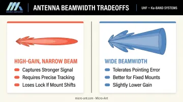
Beamwidth is your other early decision. A moderately wide beam lets you point the antenna once and leave it, since geostationary satellites drift only slightly around a fixed point in the sky. Narrow, high-gain designs (like yagis) trade that convenience for stronger signal, but they typically demand active tracking to stay locked on target.
Step 2: Source the Bill of Materials
Your parts list is short but unforgiving on quality:
- Reflector or ground plane: a common starting point for helix designs is around 8 inches in diameter, scaled from wavelength calculations at 1.5 GHz
- Conductive element: copper tubing or magnet wire for a helix, or etched copper on a PCB for a patch
- SMA bulkhead connector for a clean feed transition
- Mounting hardware rated for outdoor exposure if the antenna will live outside
- LNA with a low noise figure
- Coax cable: this is where most builds fail
Don't reuse leftover RG-58 from a Wi-Fi project. According to Times Microwave's published LMR-400 specifications, attenuation climbs from 0.7 dB per 100 feet at 30 MHz to 5.1 dB per 100 feet at 1.5 GHz. That's more than seven times the loss for the same cable run.
A 50-foot run of cheap coax at L-band frequencies can erase the gain your antenna just worked so hard to capture.
Step 3: Build and Tune the Antenna Element
Pre-form your conductive element to the target diameter and turn spacing before winding it onto the support structure. Winding cold, straight wire directly onto a mandrel stresses the material and often causes cracks or breaks at the solder joints later.
Solder the element to your SMA connector at the feed point. Feed placement is design-specific:
- Patch antennas typically use an inset feed positioned where impedance matches 50 ohms — closer to the center lowers impedance, closer to the edge raises it.
- Helix antennas are normally fed at the base near the ground plane, often with a matching strip or tapered conductor section.
Once assembled, connect a vector network analyzer and look at S11. You're hunting for a clean impedance dip at your target frequency with minimal reflection, ideally close to a 1:1 VSWR.
If the dip lands off-frequency, trim turns or adjust spacing and re-measure. This process is iterative; expect two or three rounds of small adjustments before the match settles where you want it.
Step 4: Integrate the LNA and Signal Chain
Mount your LNA as close to the antenna feed point as physically possible, ideally right behind the element itself. Cable loss between the antenna and the first active gain stage happens before amplification, so every foot of coax between the antenna and LNA works against you.
Power delivery has two common paths:
- Bias-T through an SDR or receiver: convenient, but current-limited. An Airspy R2 or Mini tops out around 50 mA, while an RTL-SDR Blog V4 supports up to 180 mA continuous
- External DC power injector: better for LNAs with higher current draw or longer indoor cable runs
Don't stack multiple LNAs in series hoping for more gain. Mismatched units can block DC bias voltage entirely, add unwanted noise, or overdrive the receiver's front end. One well-chosen LNA, correctly placed, beats two mediocre ones.
Step 5: Mount, Weatherproof, and Align the Antenna
Indoor placement is tempting, but check your windows first. A 2023 peer-reviewed study on frequency-selective glazing found Low-E glass coatings caused roughly 30 dB of average attenuation between 800 MHz and 6 GHz, a range that fully overlaps L-band.
That's enough signal loss to make indoor reception unworkable behind a Low-E window, even with a good antenna.
For outdoor mounts:
- Calculate your look angle using your location's latitude, longitude, and the satellite's orbital position
- Apply a slight downward tilt so the antenna maintains consistent gain across the satellite's daily positional drift
- Fully seal SMA connectors and enclosure seams against moisture — corrosion inside a connector is a slow, silent signal killer
Key Parameters That Affect L-Band Antenna Performance
Following the build steps gets you a physical antenna. Whether it actually performs comes down to four variables.
Polarization (RHCP vs. LHCP)
Satellite transmissions use circular polarization, and getting the sense wrong doesn't just reduce signal; it can wipe out weaker channels entirely, particularly voice traffic that needs a cleaner signal-to-noise ratio than basic data bursts.
Gain vs. Beamwidth Tradeoff
Higher-gain designs like yagis pull in stronger signal but narrow the usable beamwidth substantially:
- Captures more energy from a fixed point in the sky
- Loses lock more easily if the satellite isn't perfectly centered or your mount shifts over time
Wider-beamwidth designs trade some gain for tolerance to minor pointing error, making them more forgiving for hand-built mounts.
Frequency Tuning and Bandwidth
L-band services span multiple sub-bands, not one single frequency. An element tuned for GPS L1 (1575.42 MHz) won't necessarily perform well for Inmarsat traffic higher in the band. A detuned element raises SWR and drops received signal strength, sometimes enough that decoding software simply stops locking on.
Noise Figure and LNA Placement
In weak-signal L-band reception, the LNA's noise figure, not the receiver's, typically sets your effective noise floor. Friis' cascade noise equation explains why: later-stage noise contributions get divided down by the gain of every preceding stage. A quality first-stage LNA with a low noise figure, mounted close to the antenna, has an outsized effect on whether weak voice channels decode reliably.
What You Need Before Building Your L-Band Antenna
Before you pick up a soldering iron, confirm you have:
- Equipment: an SDR or dedicated L-band receiver, decoding software matched to your target signal (Inmarsat, ACARS, weather), and a VNA for tuning verification
- Materials: a properly sized reflector, quality connectors, and coax rated for low loss at 1-2 GHz
- Skills and site readiness: basic soldering competence, a working knowledge of your local satellite look angles, and a mounting location with an unobstructed sky view
Skipping the VNA is the most common shortcut, and it causes the most confusion later. A mistuned antenna and a bad connector produce nearly identical symptoms: weak or absent signal with no obvious cause.
Common Mistakes and Troubleshooting Tips
Most failed builds trace back to one of four issues:
- Skipped polarization verification: Building for RHCP when your design actually radiates LHCP (or vice versa) kills signal from satellites transmitting the opposite sense.
- Undersized reflector or wrong element dimensions: This misses the target frequency band entirely, even if the antenna "looks" correct.
- Low-quality or excessively long coax: L-band loss adds up fast, and a run that's fine for VHF can bleed away most of your signal budget.
- Recurring dropout tied to satellite position: If signal fades at the same point in the satellite's daily drift, suspect antenna tilt, obstruction, or polarization mismatch before assuming hardware failure.
When to Build Your Own vs. Choose a Bespoke Professional L-Band Antenna
DIY builds make sense for hobbyist reception, prototyping, and short-term experiments where some variability in performance is acceptable. You're decoding weather images or tracking Iridium bursts for fun — not keeping a fleet connected.
Mission-critical applications are a different category entirely. These demand consistent, ruggedized, certified performance:
- Defense communications requiring secure, reliable links
- Maritime tracking systems operating in harsh marine environments
- Aviation surveillance needing certified flight-line performance
- Precision GNSS positioning for centimeter-level accuracy
A homemade helix that works "most of the time" isn't good enough when a field failure has real operational cost.
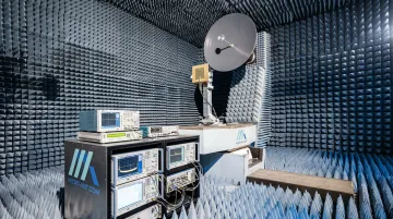
This is the space where specialized manufacturers operate differently. Micro-Ant designs bespoke L-band and GNSS antennas validated in dedicated spherical near-field test chambers covering 750 MHz to 40 GHz, a range that fully encompasses L-band. Each antenna is measured for gain, axial ratio, cross-polarization, and full envelope radiation patterns before anything ships. That's the kind of validation a hobbyist bench setup simply can't replicate.
AS9100:2016 and ISO 9001:2015 certified manufacturing matters here too. This certification means the tenth antenna off the line performs the same as the first. That consistency is exactly what procurement teams supporting DoD, satcom, and aerospace programs need to see.
If you're evaluating antennas for a regulated or high-reliability program, a hobbyist-grade build isn't the right foundation to start from. Talking to a specialized antenna design firm early in the process saves rework later.
Frequently Asked Questions
What frequency range does an L-band satellite antenna cover?
L-band spans roughly 1-2 GHz, with satellite applications typically using 0.95-2.15 GHz. That range covers GPS/GNSS, Inmarsat, Iridium, and weather satellite direct-broadcast signals.
Can I really build a working L-band antenna at home?
Yes. Simple patch or helix designs, basic tools, and a soldering iron are enough to get started. Real performance, though, depends heavily on build precision, tuning, and site conditions.
Is a helix or patch antenna better for L-band satellite reception?
Helix antennas offer higher gain and better voice-channel decoding. Patch antennas are simpler and cheaper, making them a reasonable choice for basic data reception.
Do I need a low-noise amplifier (LNA) for L-band reception?
We strongly recommend an LNA, especially indoors or for weaker channels. It offsets coax loss and lowers your system's overall noise floor, which directly affects decode reliability.
What's the difference between L-band and C-band antennas?
L-band (roughly 1-2 GHz) covers GPS, Inmarsat, and mobile satcom with small antennas. C-band (4-8 GHz) uses larger legacy dishes for fixed-satellite services with different gain requirements.
When should I use a professional antenna instead of building my own?
Mission-critical, regulated, or high-precision applications, including defense, aviation, and maritime, warrant a bespoke, professionally engineered and tested antenna rather than a DIY build. Companies like Micro-Ant design, build, and test these systems in-house for exactly these use cases.