That approach is expensive. An antenna that doesn't perform correctly can't be fixed with software updates or gain adjustments elsewhere in the chain. The physics have to be right from the start.
This article covers what engineers need to understand: the core performance parameters that define antenna behavior, the design considerations that shape every antenna decision, how to choose between off-the-shelf and custom solutions, and what testing and verification actually require.
Key Takeaways
- Gain, directivity, bandwidth, polarization, and impedance are interdependent — every design is a trade-off against application requirements
- Four pillars drive every antenna decision: operating frequency, environment, form factor, and application priorities
- Defense, satcom, and aviation applications typically require bespoke antenna designs, not off-the-shelf solutions
- Real-world testing in a controlled environment is non-negotiable; simulation alone cannot replicate field behavior
- Regulatory compliance (FCC, MIL-STD, AS9100) must be built into the design process from day one
Core RF Antenna Performance Parameters Every Designer Must Understand
Gain, Directivity, and Radiation Efficiency
Antenna gain is not additional energy injected into a signal. It's a comparative measure — how much energy is concentrated in a given direction relative to an isotropic radiator. The relationship is straightforward: G = η × D, where η is radiation efficiency and D is directivity. Gain includes losses; directivity is calculated purely from the radiation pattern. Confusing the two is one of the most common mistakes in link budget analysis.
Radiation efficiency matters because practical antennas always convert some energy into heat through resistive losses. This limits both efficiency and maximum power handling, meaning a high-directivity antenna with poor material or construction choices can still underperform on gain.
Radiation Pattern and Polarization
An antenna's 3D radiation pattern defines its usefulness for a given application. Omnidirectional patterns distribute energy in all directions; directional antennas concentrate it in a beam, with sidelobes that must be managed in interference-sensitive environments.
Polarization mismatch is a real link budget item, not a theoretical concern. The polarization loss factor is PLF = |ρ_w · ρ_a|². When transmit and receive polarizations are orthogonal, loss is theoretically infinite. In practice, NASA's analysis of a satellite data-collection link found 4.5 dB of expected polarization loss at 85% reliability with a 3 dB axial ratio — a meaningful hit on link margin that must be accounted for in satcom and airborne system design.
Linear polarization (vertical/horizontal) is common in terrestrial applications. Circular polarization (RHCP/LHCP) is standard in satellite links because it's less sensitive to antenna orientation.
Bandwidth, Resonance, and Impedance Matching
An antenna's bandwidth is the frequency range over which it maintains acceptable performance. At resonance, the reactive component of feed impedance is zero, enhancing performance in narrow-band applications. Multi-band or broadband designs require additional techniques: combining resonant structures, using fractal geometries, or carefully selecting substrates.
Impedance matching determines how much power actually transfers between the antenna and the transmission line. A mismatch produces reflections and standing waves, characterized by VSWR (voltage standing wave ratio) and return loss. Industry practice treats 10 dB return loss / VSWR 2:1 as the standard acceptable threshold — at that level, roughly 90% of power reaches the antenna.
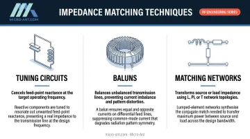
Minimizing these reflections typically involves one or more of the following:
- Tuning circuits — adjust reactive components to cancel feed-point reactance at the target frequency
- Baluns — balance unbalanced transmission lines to prevent current imbalance and pattern distortion
- Matching networks — transform impedance between source and load using L, Pi, or T topologies
Key Design Considerations in RF Antenna Design
Operating Frequency and Physical Size
Antenna dimensions scale with wavelength. A half-wave dipole is approximately λ/2 — so at UHF frequencies (300 MHz–1 GHz), element lengths run 15–50 cm. At Ka-band (27–40 GHz), wavelengths are only 5.0–11.3 mm, enabling compact apertures but introducing significant sensitivity to fabrication tolerances and material properties.
That inverse relationship directly drives antenna type selection, substrate choice, manufacturing process, and integration approach. Lower frequencies demand physically larger structures that may not fit the platform. Higher frequencies enable compact designs but require tighter dimensional control throughout fabrication.
Form Factor, Integration, and Environmental Requirements
Where the antenna sits on a platform matters as much as its inherent design. Objects within the antenna's near-field range — metal structures, ground planes, adjacent circuit blocks — cause loading effects that shift resonance, distort the radiation pattern, and degrade efficiency.
NLR's research on conformal antennas explicitly documented radiation pattern distortion caused by aircraft structure interactions, and NASA's airborne GPS work confirmed similar installed-performance deltas for different antenna forms on airframes.
Defense, aviation, and maritime antennas face additional demands:
- Temperature extremes — from arctic operations to high-altitude thermal cycling
- Mechanical shock and vibration — particularly for airborne and vehicle-mounted systems
- Humidity, salt spray, and corrosive environments — critical for maritime deployments
- Radome integration — protective enclosures preserve structural integrity but affect RF transmission characteristics and must be engineered as part of the antenna system, not as an afterthought
MIL-STD-810 governs environmental qualification for defense hardware. MIL-STD-461 addresses EMC/EMI emission and susceptibility requirements. Both cover distinct scopes — and both typically apply to fielded defense antenna systems.
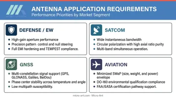
Application-Specific Performance Priorities
No two applications share the same performance hierarchy. The key differences:
| Application | Primary Priorities |
|---|---|
| Defense / EW | Gain, precise radiation pattern control, EMI hardening |
| Satellite communications | Wide bandwidth, circular polarization, multi-band capability |
| GNSS precision | Multi-constellation support, phase center stability |
| Aviation | SWaP constraints, DO-160 compliance, certification |
Feed type selection — coaxial, waveguide, transmission line — and physical placement on the platform directly affect isolation, return path integrity, and signal loss. Getting these wrong can undermine an otherwise sound design, which is why each consideration above feeds into the trade-off analysis before any fabrication begins.
Common RF Antenna Types and Their Applications
Wire, Aperture, and Patch Antennas
Three broad antenna families cover most applications:
- Wire antennas (dipole, monopole, Yagi-Uda) — suited to lower frequencies where coverage matters more than compact aperture gain; element length scales directly with wavelength
- Aperture antennas (horn, slot, waveguide) — excel at microwave and mmWave frequencies, offering high gain and wide bandwidth; WR-28 waveguide components cover the full Ka-band (27–40 GHz)
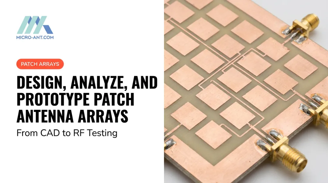
- Microstrip/patch antennas — low-profile, conformal, and integrable into aircraft skins and PCBs; bandwidth is a common limitation, though advanced substrate selection and ground-plane engineering can significantly improve on the 20 MHz / 30% efficiency typical of standard 2.4 GHz patch designs
Reflector Antennas and Phased Arrays
Reflector antennas (parabolic dishes, tri-band segmented designs) convert spherical waves into collimated beams, substantially increasing directivity. They are the preferred solution for long-range satellite communications and fixed-link applications where physical size is acceptable.
Phased array antennas achieve electronic beam steering without mechanical movement — a capability reflector designs cannot match. Arrays of smaller elements with controlled phase shifters enable beamforming for communications (MIMO, multi-orbit satellite) and sensing (radar).
Key specifications for aerospace and defense phased arrays include:
- Transmit band: 27–31 GHz (Ka-band)
- Receive band: 17.5–20.5 GHz (Ka-band)
- Active arrays: higher front-end complexity and cost, but unmatched for fast beam repositioning in dynamic environments
That beam-steering flexibility directly informs the omnidirectional vs. directional trade-off. Omnidirectional antennas suit mobile platforms that need consistent signal regardless of orientation; high-gain directional antennas are the right choice for fixed links or long-range satcom. Many demanding applications require both, often in electronically switchable configurations.
Off-the-Shelf vs. Custom Bespoke Antenna Design: Making the Right Call
When Standard Antennas Are Sufficient
Off-the-shelf antennas offer real advantages: lower cost, immediate availability, and shorter time to deployment. When a program's frequency, bandwidth, gain, environmental, and platform requirements fall well within the capabilities of existing catalog designs, standard solutions are entirely appropriate.
The key caveat: even catalog antennas require careful evaluation and testing in the actual system before committing to production. Installed performance can differ substantially from free-space datasheet figures.
When Standard Antennas Fall Short
Demanding applications routinely push outside what catalog designs can deliver. Common drivers for custom antenna development include:
- Non-standard frequency bands — Q/V-band, ultra-wideband Ka systems, or simultaneous multi-band operation
- Unique radiation pattern requirements — conformal installation on aircraft surfaces, precise null placement for EW systems
- Platform-specific geometry — aircraft fuselages, ship hulls, or vehicle mounts that influence installed performance
- Extreme SWaP constraints — UAV and airborne systems where every gram and cubic centimeter is accounted for
- MIL-SPEC environmental performance — temperature, shock, vibration, and EMI requirements that exceed commercial-grade designs
- Multi-orbit satellite tracking — simultaneous GEO, MEO, and LEO compatibility demands antennas that standard designs weren't built for
The Custom Antenna Design Process
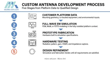
Custom antenna development is an iterative engineering process, not a single-pass design exercise. The typical workflow:
- Customer provides platform data — CAD models, mounting geometry, co-located equipment, and environmental requirements
- Full-wave EM simulation — FEM, MoM, or FDTD solvers model the antenna in its installed context, not just in free space
- Prototype fabrication — initial hardware built to simulation-derived specifications
- Hardware testing — near-field or far-field measurement captures actual radiation pattern, gain, VSWR, and impedance
- Design refinement — simulation and fabrication iterate until measured performance meets requirements
This process requires experienced RF engineers and calibrated EM simulation tools. Antenna designs are sensitive to fabrication tolerances and real-world surroundings in ways that only hardware testing can fully characterize.
Micro-Ant's Bespoke Antenna Design Approach
Micro-Ant, based in Jacksonville, Florida, is a bespoke antenna design and manufacturing firm with over 20 years of experience serving defense, aviation, maritime, and satellite communications programs. AS9100:2016 and ISO 9001:2015 certified, the company operates a 65,000 sq ft facility with design, fabrication, and testing conducted in-house.
Their portfolio spans more than a thousand bespoke products — including the award-winning Ultra-Wide Band Ka Antenna System (2022 Innovation of the Year and SatCom Technology of the Year) and high-precision GNSS designs serving agriculture, construction, and logistics. Major customers include satellite operators across GEO, MEO, and LEO constellations, as well as DoD and intelligence community programs.
For programs that have outgrown catalog options, Micro-Ant's in-house design-build-test model supports development from initial CAD data through prototype, environmental qualification, and production at scale — without handoffs between vendors.
Antenna Simulation, Testing, and Verification Best Practices
Why Simulation Alone Is Not Enough
EM simulation tools — whether FEM solvers like Ansys HFSS or hybrid-method platforms like Simcenter Feko — have become highly accurate and enable parametric design optimization before any hardware is cut. But no simulation perfectly replicates real-world behavior. Fabrication tolerances, nearby structures, actual material properties, and mounting geometry all introduce performance deltas that only hardware measurement can reveal.
This isn't a limitation of simulation quality. It's a physics reality: the installed antenna is a different electromagnetic object than the isolated design in the solver.
Testing Methods and Environments
Controlled-environment testing falls into two primary categories:
- Far-field testing — direct radiation pattern measurement at or beyond the Fraunhofer distance (R ≥ 2D²/λ); straightforward for smaller antennas at lower frequencies
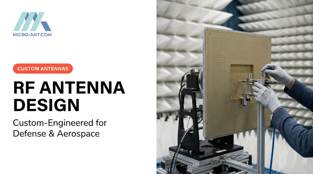
- Near-field testing — probe arrays mathematically reconstruct the 3D radiation pattern; necessary for large apertures or high-frequency arrays where far-field range distance is impractical
Both require electromagnetically isolated environments — anechoic chambers with absorptive interiors or calibrated open-air test ranges — to prevent environmental reflections from contaminating measurements. IEEE Std 149-2021 is the authoritative recommended practice for antenna measurement and test facility design.
Micro-Ant's Jacksonville facility includes calibrated spherical and planar near-field testing chambers covering 750 MHz to 40 GHz, accommodating antennas up to 2 meters with full 360° × 360° pattern coverage. For US-based programs, this eliminates the cost and schedule impact of shipping hardware to offshore test facilities.
Regulatory Compliance Testing
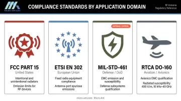
Most fielded RF systems require formal compliance testing before they can be sold or deployed:
- FCC Part 15 — covers intentional and unintentional radiators operating without individual licenses; sets emission limits that directly affect antenna design choices
- ETSI EN 302 — European fixed-radio compliance, including antenna-port spurious emission requirements
- MIL-STD-461 — EMC emission and susceptibility requirements for defense subsystems and equipment
- RTCA DO-160 — avionics environmental and EMC qualification, covering radiated susceptibility up to 400 V/m across 10 kHz to 40 GHz
The GAO has noted that early spectrum assessment gives DoD programs the opportunity to identify and resolve regulatory and technical issues during acquisition, before they become schedule and cost problems. Antennas caught out of compliance at the end of the design cycle routinely require redesign, retesting, and schedule slippage — all avoidable with iterative compliance checks built into the development process.
Frequently Asked Questions
What is the most important performance parameter in RF antenna design?
There's no single answer — the right balance depends entirely on the application. That said, impedance match, gain, bandwidth, and radiation pattern are consistently the most consequential because they directly determine how well the antenna transfers energy between the system and free space. Get those wrong and nothing else compensates.
How does operating frequency influence RF antenna size and design?
Antenna dimensions are inversely proportional to frequency — element length scales with wavelength. Lower frequencies like UHF require physically large structures, while Ka-band (27–40 GHz) enables compact apertures. At higher frequencies, fabrication tolerances become critical: small dimensional errors produce significant performance shifts.
When should you choose a custom antenna over an off-the-shelf solution?
Custom antennas are warranted when application requirements — non-standard frequency bands, extreme environmental conditions, unique platform geometry, multi-band capability, or strict SWaP constraints — exceed what catalog designs can reliably deliver. If the datasheet doesn't match your requirements exactly, it probably won't in the field either.
What is impedance matching and why does it matter in RF antenna design?
Impedance matching ensures maximum power transfer between the antenna and its feed line by minimizing signal reflections. A mismatch causes energy to reflect back toward the transmitter or receiver, reducing range, efficiency, and system reliability. VSWR and return loss are the standard metrics. A 10 dB return loss (VSWR 2:1) benchmark means roughly 90% of power reaches the antenna.
How are RF antennas tested and validated before deployment?
Antennas are measured in anechoic chambers or open-air ranges using near-field or far-field setups. These capture the full 3D radiation pattern, gain, VSWR, and impedance. Iterative test-refine cycles are standard: simulation establishes design direction, but hardware testing reveals what actually happens in a real environment.
What environmental factors matter most for defense or aerospace antennas?
The primary concerns include temperature extremes, mechanical shock, vibration, humidity, salt spray, and corrosive exposure. Material selection, structural engineering, and radome design must address these simultaneously. Qualification against MIL-STD-810, MIL-STD-461, AS9100, and DO-160 provides documented evidence that a design will survive in the field.