Many engineers and procurement teams struggle with a basic problem: distinguishing a true UWB antenna from a standard "wideband" design. Get it wrong, and you end up with poor frequency coverage, failed FCC certification, or a system that simply doesn't meet spec.
This guide breaks down what actually defines a UWB antenna, how these systems work, the major design architectures in use today, real-world applications, and what to look for in a bespoke UWB antenna partner.
Key Takeaways
- True UWB antennas need bandwidth over 500 MHz or 20% of center frequency, per FCC and ITU-R rules
- UWB positioning achieves centimeter-level accuracy, outperforming Bluetooth and Wi-Fi ranging
- Form factor (Vivaldi, horn, spiral, monopole) hinges on gain, size, and bandwidth needs
- Bespoke engineering is essential for defense, aerospace, and satcom systems where catalog antennas fall short
What is an Ultra-Wideband (UWB) Antenna?
A UWB antenna is built to transmit and receive across an exceptionally wide frequency range, typically spanning more than an octave. Compare that to conventional antennas, which usually operate across just 20-30% bandwidth relative to their center frequency.
The Regulatory Definition Actually Matters
Under FCC rules, a signal only qualifies as UWB if its -10 dB bandwidth meets one of two thresholds:
- 500 MHz or greater in absolute bandwidth, OR
- 20% or greater fractional bandwidth relative to the center frequency
ITU-R applies substantially the same test. That means a datasheet claiming "wideband" performance with a large VSWR bandwidth doesn't automatically qualify as UWB. Procurement teams should request a measured -10 dB bandwidth plot, not just a marketing spec sheet.
Spectrum Allocation Varies by Region
The FCC allocates 3.1-10.6 GHz for unlicensed indoor and handheld UWB use in the US. Europe's ECC framework splits this differently, with a generic high-power UWB band sitting at 6.0-8.5 GHz and adjacent sub-bands requiring mitigation techniques like duty-cycle limiting or detect-and-avoid. An antenna tuned for US deployment won't automatically pass European compliance testing.
Why "Frequency Independent" Comes With a Trade-Off
UWB antennas are sometimes called frequency independent antennas because their geometry (not resonant length) determines bandwidth. That broad coverage comes at a cost: narrowband antennas naturally filter out-of-band interference, while UWB antennas typically don't get that benefit and need additional filtering elsewhere in the system. Micro-Ant's engineers face this trade-off directly when building UWB Ka-band systems, including the design that earned the company a 2022 Innovation of the Year award for its 3.5 GHz Ka antenna system.
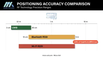
The payoff is precision. A 2023 peer-reviewed indoor localization review found UWB positioning accuracy in the 3-30 cm range, compared to 10 cm to nearly 5 meters for Bluetooth RSSI and similarly wide ranges for Wi-Fi RSSI. That's not a marginal improvement. It's an order-of-magnitude difference in positioning fidelity.
How Do UWB Antennas Work?
Conventional radios vary the amplitude, frequency, or phase of a sinusoidal carrier wave. UWB systems work differently: they transmit information as short radio energy pulses across precise time intervals, using techniques like pulse-position modulation and time hopping.
This pulse-based approach spreads transmit power thinly across a huge slice of spectrum. The result is a signal that coexists with narrowband users occupying the same frequencies without causing meaningful interference.
Four Positioning Techniques Built on UWB Timing
UWB antennas enable several ranging methods, each suited to different deployment scenarios:
- Time of Flight (ToF) - measures propagation delay to calculate distance directly
- Time Difference of Arrival (TDoA) - synchronized anchors compare arrival times to locate a tag
- Two-Way Ranging (TWR) - exchanges messages bidirectionally, easing clock-sync requirements
- Phase Difference of Arrival (PDoA) - compares phase across multiple antennas to estimate angle of arrival
NIST testing on a TWR-based system reported mean absolute error of just 0.08 m outdoors in line-of-sight conditions and 0.28 m in an indoor corridor. Wi-Fi RTT covered longer distances but with noticeably less precision.
Multipath resistance comes down to timing resolution. Because UWB pulses are so short, receivers can resolve fine timing differences between the direct signal and reflected paths bouncing off walls or equipment. This lets the system isolate the line-of-sight component in cluttered environments where narrowband signals would simply blur together. Metal obstructions and severe non-line-of-sight conditions still introduce bias, so this isn't a cure-all.
Strict power limits make coexistence possible. The FCC caps UWB mean emissions at -41.3 dBm/MHz across the 3.1-10.6 GHz band, with a 0 dBm peak limit in any 50 MHz window. That extremely low power spectral density is what allows UWB devices to share spectrum with existing users without licensing.
Types of UWB Antenna Designs
Choosing an antenna geometry depends on required gain, directivity, size constraints, and polarization. No single design wins across every application.
Tapered Slot (Vivaldi) Antennas
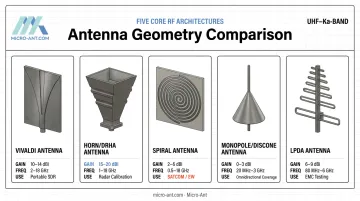
Vivaldi antennas look like a 2D slice of a horn, etched directly onto a PCB. They're compact, moderate-gain, and popular for portable SDR platforms and sensing applications where board space is limited. Two-element monopulse Vivaldi arrays have demonstrated sum gain above 10 dBi across the full 3.1-10.6 GHz band.
Horn and Dual-Ridged Horn Antennas (DRHA)
Large-aperture horn designs deliver high gain at high frequencies, which is why they're a common choice as calibration standards in test chambers and radar systems. Commercial double-ridged horns cover roughly 1-18 GHz with VSWR under 1.5:1, making them dependable reference antennas for EMC and radar testing labs.
Spiral Antennas
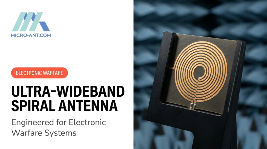
Archimedean and logarithmic spiral geometries produce circular polarization with consistent gain along the boresight axis. That polarization diversity matters in satcom and electronic warfare applications, where signal orientation isn't predictable. Conical log spirals typically span 1-10 GHz with average VSWR near 1.6:1.
Monopole/Dipole and Discone Antennas
PCB-printed circular or elliptical monopole elements, along with wire discone structures, provide omnidirectional UWB coverage. These work well when a single mast-mounted antenna needs to cover broad spectrum without directional bias. Planar monopoles have shown gain around 4.1 dBi with 75% average efficiency across 3.1-18.6 GHz.
Log-Periodic Dipole Arrays (LPDA)
LPDAs use progressively sized elements to maintain stable gain across a wide frequency range. That predictability is exactly why they're standard equipment in EMC testing labs and surveillance receivers, even though most commercial LPDA models cover sub-2 GHz ranges rather than the full UWB spectrum.
These five geometries serve as engineering starting points. Micro-Ant's engineering team treats them as foundational architectures, then customizes gain, pattern, and polarization to match a specific platform's constraints rather than pulling from a catalog.
Applications and Design Considerations for UWB Antennas
Where UWB Antennas Are Used
UWB hardware shows up across a surprisingly wide range of industries:
- Defense and radar - through-wall imaging, ground-penetrating radar, and precision target detection, where NIST's robot-mounted SAR system achieved 2.5 cm resolution using 6 GHz of bandwidth
- Real-time locating systems (RTLS) - asset tracking in industrial, logistics, and construction settings, where centimeter accuracy cuts downtime and reduces losses
- Consumer and automotive - secure keyless entry, device-to-device ranging for locator tags, and collision-avoidance sensing in autonomous vehicles
One vendor-documented RTLS deployment involving 40 anchors and 600 tags across 2,000 square meters reported a 50% reduction in lead time, though results like this depend heavily on site-specific installation conditions.
Key Engineering and Regulatory Challenges
These capabilities don't come without engineering hurdles. Three challenges consistently come up in UWB antenna programs:
Gain-bandwidth-size tradeoff - achieving high gain and ultra-wide bandwidth in a compact footprint pushes against fundamental antenna physics. There's no shortcut around this; it requires iterative design and simulation.
Regional regulatory compliance - FCC and ECC power masks differ substantially by sub-band, and FCC rules prohibit UWB operation aboard aircraft, ships, or satellites entirely. A design cleared for one market may need rework for another.
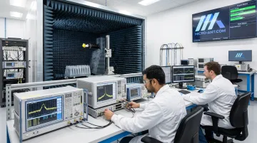
Rigorous performance validation - near-field and far-field testing across hundreds of MHz to tens of GHz confirms real-world behavior matches simulation. In-house chambers spanning 750 MHz to 40 GHz, like Micro-Ant's, cut qualification time compared to third-party lab turnaround.
Why Choose Micro-Ant for Bespoke UWB Antenna Solutions
Micro-Ant's Ultra-Wide Band (3.5 GHz) Ka Antenna System earned the 2022 Innovation of the Year and SatCom Technology of the Year awards in the Most Innovative category. Meeting the axial ratio requirement of less than 1 dB across the full band on both receive and transmit required new engineering techniques developed specifically for this program. Manufacturing innovations were also needed to hold tolerances on critical components.
That kind of problem-solving reflects how Micro-Ant approaches every custom antenna program:
- Over 20 years of antenna design experience serving defense, aviation, maritime, and land customers
- AS9100:2016 and ISO 9001:2015 certified manufacturing based in Jacksonville, Florida
- A portfolio of 1,000+ bespoke antenna products, built without reliance on off-the-shelf templates
Rather than outsourcing validation and waiting on third-party lab schedules, Micro-Ant runs qualification testing in its own dedicated high-performance testing facility. For clients working against defense or satcom program deadlines, that in-house capability translates into fewer shipping delays and faster answers when a design needs adjustment.
Frequently Asked Questions
What is an ultra-wideband antenna?
A UWB antenna is engineered to transmit and receive across a bandwidth exceeding 500 MHz or 20% of its center frequency. This wide bandwidth enables precise short-range positioning and high-bandwidth data transfer that narrowband antennas can't match.
What is the maximum range of UWB?
Effective UWB range typically runs from tens of meters up to around 100 meters in line-of-sight conditions, depending on power limits and obstacles. UWB's real strength is positioning accuracy, not long-range coverage.
Is UWB safe for humans?
Yes. UWB operates under strict FCC power spectral density limits (-41.3 dBm/MHz), well below levels of concern, making it suitable for continuous proximity use in consumer and industrial devices alike.
What frequency band does UWB use?
In the US, the FCC allocates 3.1-10.6 GHz for unlicensed UWB operation. Europe's ECC framework splits this into sub-bands like 3.1-4.8 GHz and 6-9 GHz, each with different power allowances.
How is UWB different from Bluetooth or Wi-Fi for positioning?
UWB uses time-based pulse ranging to achieve centimeter-level accuracy. Bluetooth and Wi-Fi rely on signal strength estimation, which typically yields meter-level accuracy at best.
What industries benefit most from custom UWB antenna design?
Defense, aerospace, satcom, automotive, and industrial IoT sectors see the biggest gains from bespoke UWB antennas, since generic designs often can't meet the gain, size, or environmental demands these applications require.