Introduction
A satellite terminal with a flawless radio and a poorly matched antenna will still drop the link. That's the uncomfortable truth many RF and communications programs learn the hard way: no amount of downstream processing power fixes a radiating element that wasn't designed or tested correctly.
Yet antenna work often gets treated as a checkbox task, squeezed in after the "real" electronics are finalized. The result is field failures in harsh defense, aviation, and maritime environments, missed certifications that delay shipment, and redesigns that blow through budget and schedule.
None of this is inevitable. This guide walks through the full lifecycle: the fundamentals that govern performance, the design process from concept to prototype, and common antenna types. It also covers how testing actually happens, why skipping it gets expensive, and what to look for in a design-and-test partner.
Key Takeaways
- Polarization mismatch alone can cost 3+ dB of signal, making alignment as critical as raw gain
- A well-matched antenna keeps VSWR near 1:1, minimizing power lost to reflection
- Simulation shortens design cycles, but physical prototyping and range testing stay non-negotiable
- Environmental and EMC testing prevent field failures on defense, aviation, and maritime platforms
- In-house design-to-test capability cuts turnaround time versus shipping units offsite for validation
Understanding Antenna Design Fundamentals: Key Performance Criteria
An antenna is a transducer, nothing more and nothing less. It converts electrical signals into electromagnetic waves for transmission, and electromagnetic waves back into electrical signals on receive. Every design decision, from material to geometry to feed structure, ripples through the rest of the system long after the antenna leaves the bench.
Polarization and Radiation Pattern
Polarization describes the orientation of the electric field as a wave propagates. Linear polarization keeps that orientation fixed; circular polarization rotates it. A mismatch between antenna and signal polarization carries a direct cost, showing up as a measurable tax on link budget.
Couple an ideal linear antenna to an ideal circularly polarized signal, and you lose half the available power: 3.01 dB, according to Keysight's antenna radiation pattern reference. Orthogonal circular senses, right-hand versus left-hand, couple almost no power at all.
Gain and directivity describe how tightly an antenna focuses energy. An isotropic radiator, a theoretical sphere radiating equally in all directions, is the baseline for comparison. Real antennas concentrate energy into a directional pattern instead, trading beamwidth for range: a narrow, high-gain beam reaches farther but demands more precise pointing than a broad, low-gain pattern.
Impedance Matching, VSWR, and Bandwidth
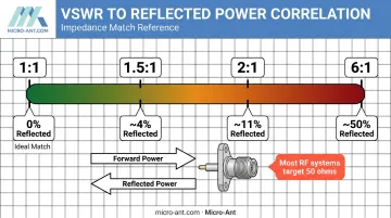
Impedance matching keeps energy moving forward instead of bouncing back into the system. A mismatch reflects power at the interface, and that reflected energy shows up as heat, noise, or reduced range.
Return loss and VSWR both quantify this reflection:
- VSWR of 1.5:1 reflects about 4% of power back toward the source
- VSWR of 6:1 reflects roughly 50% of power, per Rohde & Schwarz's VSWR and return loss guide
- Most RF systems target impedance near 50 ohms
- A perfect match yields a VSWR of 1:1, with essentially zero reflected power
Bandwidth determines how much frequency range an antenna covers without retuning. Extended and ultra-wideband designs matter here. Micro-Ant's Ultra-Wide Band (3.5 GHz) Ka Antenna System, for example, was built specifically so terminals can roam across multiple satellite operators' frequency segments without swapping hardware in the field.
Power Handling and Environmental Ruggedness
None of this matters if the antenna cracks under a helicopter's vibration profile or drifts out of spec in desert heat. Power handling and ruggedness are baseline requirements for defense, aviation, and maritime platforms, which regularly face:
- Extreme temperature swings, from arctic cold to engine-bay heat
- Continuous shock and vibration during vehicle, aircraft, or vessel operation
- Salt fog, humidity, and occasional immersion in maritime environments
- Long service life with minimal maintenance access
These are baseline operating conditions that every platform in these markets will encounter. Ruggedness has to be a design input from day one, built into material selection and structural tolerances before the first prototype ships.
The Antenna Design Process: From Concept to Working Prototype
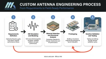
Every antenna design starts with the same question: what does this application actually need? Frequency band, host platform (vehicle, vessel, aircraft, handheld), operating environment, and integration constraints such as size, weight, and mounting all define the space engineers design inside. Skipping this step guarantees rework later.
Electromagnetic Simulation and Modeling
Before anyone touches a fabrication tool, the design lives inside full-wave EM simulation software. Micro-Ant's engineers run these models on platforms like Ansys HFSS and CST Studio Suite, testing radiation pattern, gain, and impedance across the full frequency range so geometry changes take hours instead of weeks.
Parametric optimization takes this further. Sweep a dimension, feed position, or material property across a range of values, and let the solver find the combination that hits target performance. This virtual prototyping shortens development cycles, though the real value comes from engineers who know which results to trust and which need bench verification.
Material Selection and Structural Analysis
Material choice affects electrical performance and mechanical survival at the same time. Dielectric substrates set loss and bandwidth. Radome materials need low dielectric constant and low loss tangent so they don't distort the signal passing through. They also need to survive fuel exposure, saltwater spray, and years of UV without degrading.
Engineers complete structural and static analysis before cutting any metal, modeling how housings and mounts respond to shock, vibration, and thermal cycling. This step catches flaws like a mounting bracket that resonates at the wrong frequency while it's still cheap to fix.
Prototyping and Iterative Validation
Simulation gets you close. It doesn't get you finished. A physical prototype validates behavior no solver fully captures, including near-field coupling effects and how the antenna performs once mounted on the actual platform.
Prototyping also surfaces practical questions simulation can't answer: can this be assembled reliably at volume, and does the bill of materials hold up cost-wise at production scale? Iteration between prototype and test data, adjusting, rebuilding, remeasuring, continues until the design meets spec repeatably across units, not just once on a bench. At Micro-Ant, that loop holds across production runs from 5 to 200,000+ units a year, so repeatability matters as much as raw performance.
Common Antenna Types and Choosing the Right Design
Not every application calls for the same antenna architecture. Four categories cover most bespoke, custom work:
| Type | Best suited for | Key trade-off |
|---|---|---|
| Reflector/parabolic | High-gain SATCOM, radar, multi-mission terminals | Higher directivity means larger size and tighter pointing tolerance |
| Phased array | Beam steering without moving parts for EW, mobile SATCOM, tracking | Faster, flexible beams cost more power, heat, and complexity |
| Horn/aperture | Wideband applications and calibration references | Broad bandwidth trades against physical length and limited steering |
| Patch/GNSS | Low-profile, conformal integration on vehicles and handhelds | Compact and inexpensive, but lower gain and narrower bandwidth |
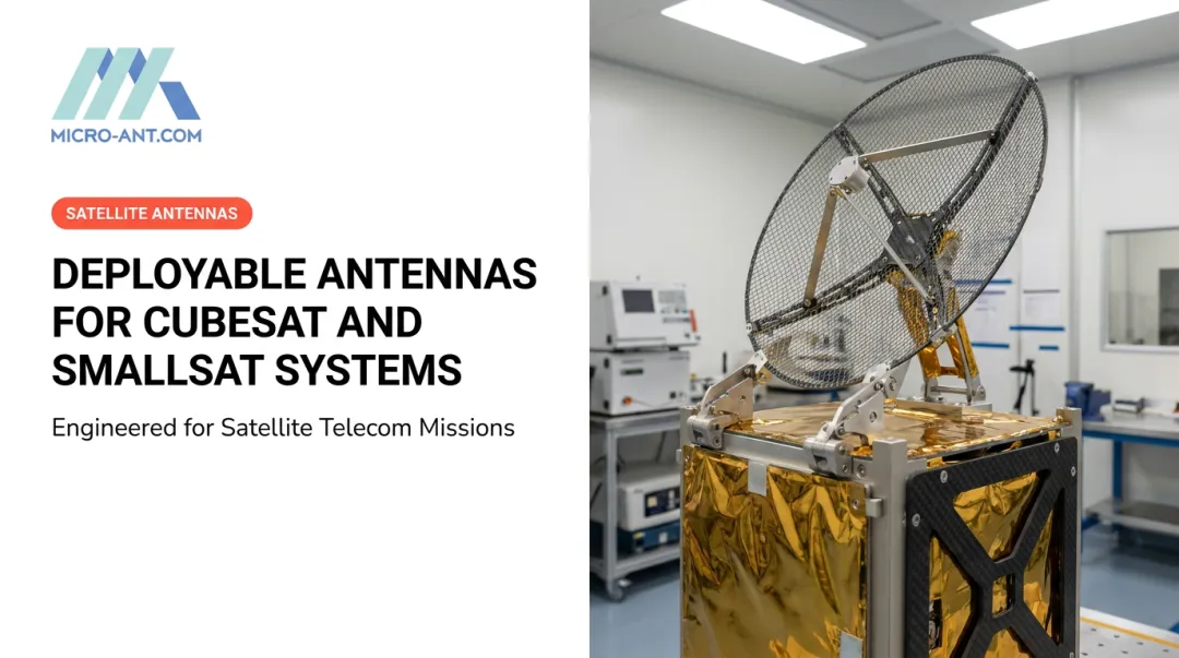
The application decides the type, not the other way around. A multi-mission SATCOM terminal might call for a tri-band segmented reflector, the kind used in manpack and flyaway field terminals, where signal strength and field durability both matter. A positioning-critical system needs a compact, high-precision GNSS patch antenna instead, where mounting footprint matters more than raw gain.
Every choice comes down to the same three trade-offs:
- Directivity versus beamwidth
- Size versus bandwidth
- Cost versus performance
Getting this balance wrong early is one of the most common reasons bespoke antenna projects need a second design pass.
How Antennas Are Tested: Methods, Equipment, and Facilities
Simulation predicts. Testing confirms. No solver perfectly models near-field coupling, cable routing, or how an antenna behaves once bolted onto an actual aircraft, vessel, or vehicle, which is why physical testing stays mandatory even after a design passes every simulated benchmark.
Anechoic Chamber and Near-Field Testing
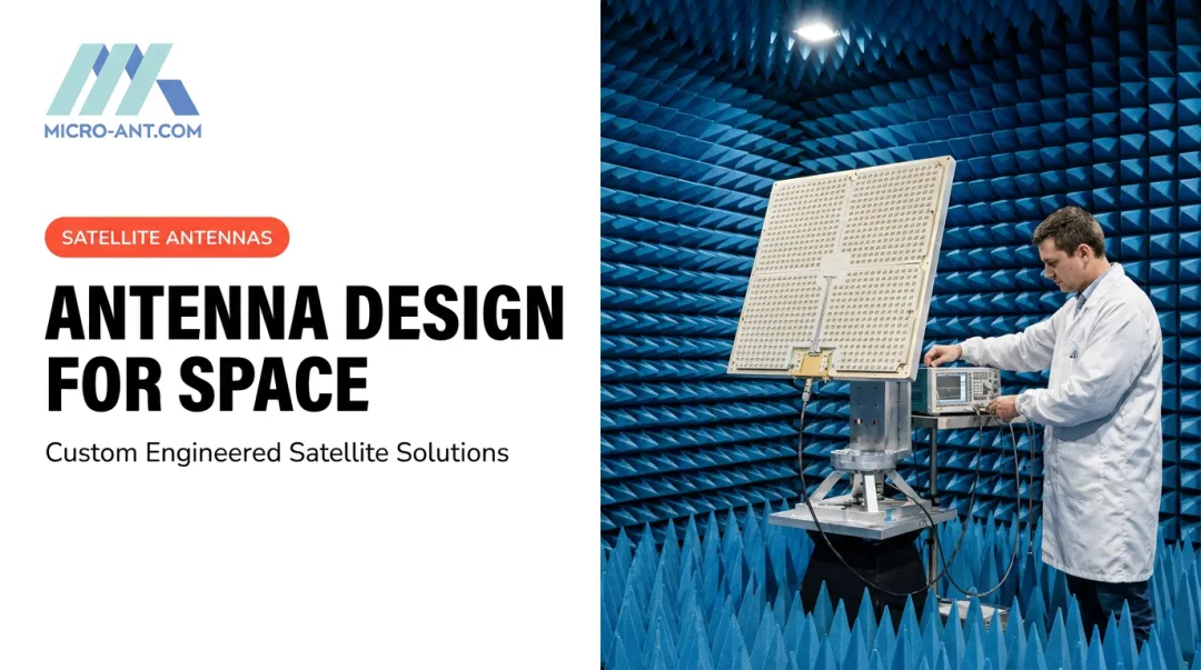
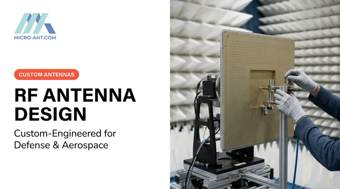
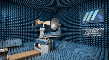
An anechoic chamber is an electromagnetically isolated room lined with RF absorber, built so outside signals and internal reflections don't contaminate the measurement. Inside that quiet zone, engineers measure gain, radiation pattern, and efficiency with confidence that they're seeing the antenna, not the room.
Two measurement geometries dominate testing:
| Geometry | Best Suited For |
|---|---|
| Planar near-field scanning | Highly directive antennas scanned across a flat plane |
| Spherical near-field scanning | Broad-beam antennas, sampling radiation from all directions |
Both approaches measure close to the antenna, then mathematically transform that data into the far-field pattern engineers actually need. Micro-Ant runs both spherical and planar near-field chambers in-house, covering 750 MHz to 40 GHz. That range covers everything from tactical UHF hardware through Ka-band SATCOM systems, without shipping units to an outside range.
Impedance and Environmental Testing
Impedance verification uses a network analyzer to sweep S11 across every operating band, converting the result into return loss and VSWR. Matching to system impedance, commonly 50 ohms, gets confirmed here rather than assumed.
Electrical performance is only half the story. Environmental and ruggedness testing puts the antenna through the conditions it will actually face:
- Shock and vibration testing for vehicle, aircraft, and vessel mounting
- Thermal cycling across the full operating temperature range
- Humidity and salt exposure testing for maritime and outdoor deployments
- Extended duty-cycle testing under sustained power loads
Compliance and certification testing, covering EMC/EMI and regional spectrum regulations, comes last. It's the gate that determines whether a product can ship or sell in a given market. Skipping it doesn't remove the requirement; it just moves the failure downstream to a customer's dock or a regulator's desk.
Why Rigorous Testing Matters: Performance, Cost, and Risk
Testing isn't a formality. It has a direct, calculable effect on both system performance and program risk.
Gain translates directly to coverage. A 3 dB gain improvement delivers measurable, calculable benefits (FCC propagation guidance):
- Roughly doubles received power at a fixed range under standard line-of-sight assumptions
- Extends range by about 1.4x when the receiver threshold stays constant, nearly doubling coverage area
That's the difference between a link that holds and one that drops at the edge of a mission area.
Skipping or shortcutting testing doesn't remove risk. It just defers it to later, more expensive stages, typically showing up as:
- Field failures that surface after deployment
- Costly redesigns that eat schedule and budget
- Missed certification windows that delay milestones
Government and commercial programs alike have learned this lesson repeatedly, catching quality issues during operational use that a proper test regimen would have caught on the bench first.
There's also a practical dimension teams often underestimate: travel. Shipping units overseas for range time adds weeks of transit, customs delays, and scheduling friction on top of the test itself.
A domestic, quick-turnaround facility, like Micro-Ant's in-house chambers in Jacksonville, keeps test data close to the engineers who need to act on it, cutting cost and calendar time from the validation loop.
Choosing the Right Antenna Design and Testing Partner
Choosing a design-and-test partner comes down to three questions: can they prove quality, can they design and validate under one roof, and has anyone beyond the company itself confirmed the results?
Certifications matter first. Look for ISO 9001:2015 as a baseline quality management standard, and AS9100:2016 specifically if the application touches aviation, space, or defense. AS9100 builds on ISO 9001 with added requirements for:
- Full material and component traceability
- Documented risk management processes
- Counterfeit-part prevention protocols
In-house simulation-to-test capability matters second. A partner who designs in simulation, builds the prototype, and validates it on their own range avoids the handoff delays and data gaps that come from outsourcing each stage to a different vendor.
Micro-Ant is one example of this model. The company has spent over 20 years designing and manufacturing bespoke antennas for defense, aviation, maritime, and land applications. It has delivered more than 1,000 custom products from its 65,000-square-foot Jacksonville, Florida facility.

Its in-house spherical and planar near-field test chambers span 750 MHz to 40 GHz, covering everything from tactical UHF hardware to Ka-band SATCOM systems without sending units offsite.
Beyond in-house testing, third-party recognition also helps validate engineering credibility beyond a company's own claims. Micro-Ant's Ultra-Wide Band (3.5 GHz) Ka Antenna System won the Satcoms Innovation Group's 2022 Innovation of the Year award. That kind of validation matters when a program can't afford a redesign.
Frequently Asked Questions
Which software is best for antenna design?
Full-wave EM solvers like Ansys HFSS and CST Studio Suite are industry standards for modeling pattern, gain, and impedance. Software matters less than the engineer's experience interpreting and validating those results against physical measurements.
Is antenna design difficult?
Building a basic antenna is straightforward. Hitting specific gain, bandwidth, ruggedness, and certification targets for a demanding platform requires specialized expertise and iterative rounds of testing to hit those targets.
How are antennas tested?
Core methods include anechoic chamber measurements for pattern and gain, network analyzer sweeps for impedance and S11, and environmental testing for shock, vibration, thermal cycling, and humidity. Certification testing for EMC and spectrum compliance typically follows.
What is the difference between near-field and far-field antenna testing?
Near-field testing measures close to the antenna, then mathematically transforms that data into the far-field pattern. Far-field testing measures the radiating plane wave directly, but usually requires more distance than most ranges have available.
How long does it take to design and test a custom antenna?
Simple designs can move from concept to first article in a few weeks, while complex phased-array or certification-heavy programs often take several months. Working with a partner who handles simulation, prototyping, and testing in-house shortens that cycle compared to outsourcing each stage separately.
What certifications should I look for in an antenna manufacturer?
ISO 9001:2015 signals a solid quality management system. AS9100:2016 adds aviation, space, and defense-specific requirements around traceability and risk management, so look for both if your program touches government or aerospace work.