Program managers and RF engineers evaluating horn antennas face a real challenge, though. Picking the wrong horn type, aperture size, or manufacturing partner can mean failed qualification tests, schedule slips, or degraded mission performance. Many engineers struggle to match horn geometry to frequency band, beamwidth, and environmental requirements before a design ever reaches a test chamber.
This guide breaks down how horn antennas work, the types used across defense and aerospace programs, their performance advantages, where they show up in fielded systems, and what to look for in a manufacturing partner.
Key Takeaways
- Horn antennas deliver 10-25 dBi gain with low loss for radar, SATCOM, and EMC applications
- Five horn families (pyramidal, conical, sectoral, corrugated, ridged) target different mission needs
- No moving parts ensure better survivability under shock, vibration, and extreme temperatures
- In-house near-field/far-field testing speeds qualification versus third-party labs
- AS9100:2016 and ISO 9001:2015 certifications signal defense-grade manufacturing
What Is a Microwave Horn Antenna?
A horn antenna is a flared section of waveguide that gradually transitions microwave energy from a confined guided mode into a radiated free-space wave. It works as a transmitter or receiver across microwave and millimeter-wave frequencies, and it's one of the most predictable, well-understood antenna designs in the RF world.
Every horn antenna has three core parts:
- Feed waveguide: Carries the guided electromagnetic wave from the transmitter or receiver
- Flare (taper) section: Steadily widens the cross-section to reduce the abrupt impedance discontinuity between the waveguide and open space
- Aperture: The open end where energy radiates outward (or is collected on receive)
How Horn Antennas Work
The flare exists to solve an impedance problem. Free space carries an intrinsic wave impedance of roughly 377 ohms, while a waveguide's characteristic impedance is different and frequency-dependent. Without a gradual transition, energy reflects back into the feed, raising the voltage standing wave ratio (VSWR) and wasting power.
The horn's taper smooths that transition, which is why VSWR and return loss numbers on a horn's datasheet matter more than any single "377-ohm" claim. A well-matched horn feed maintains low reflected power across its entire operating band, not just at one frequency point.
Aperture size and taper length also set the beam. Larger apertures produce higher directivity and narrower beamwidths, while shorter tapers for the same aperture size increase flare angle and introduce phase error across the aperture. Engineers balance these two variables against physical length constraints on the platform.
A Legacy Rooted in Defense Innovation
Horn antenna history traces to MIT engineer Wilmer Lanier Barrow, who demonstrated a working electromagnetic horn design in 1938. He launched microwave energy from a square hollow tube into a flared throat to produce a narrow beam (MIT Museum). His theoretical work on wave propagation in hollow metal tubes and horn radiation proved critical to the microwave radar systems developed during World War II.
That legacy hasn't faded. Horn antennas still serve as SATCOM feeds, EW sensors, and radar calibration standards on modern platforms.
Types of Horn Antennas Used in Defense and Aerospace
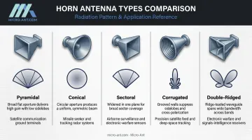
Mission requirements dictate horn selection. Frequency band, beamwidth, polarization, and sidelobe control all factor into which geometry fits a given platform.
| Horn Type | Key Characteristic | Common Defense/Aerospace Use |
|---|---|---|
| Pyramidal | Rectangular aperture, flared in both planes | Radar systems, standard-gain calibration references |
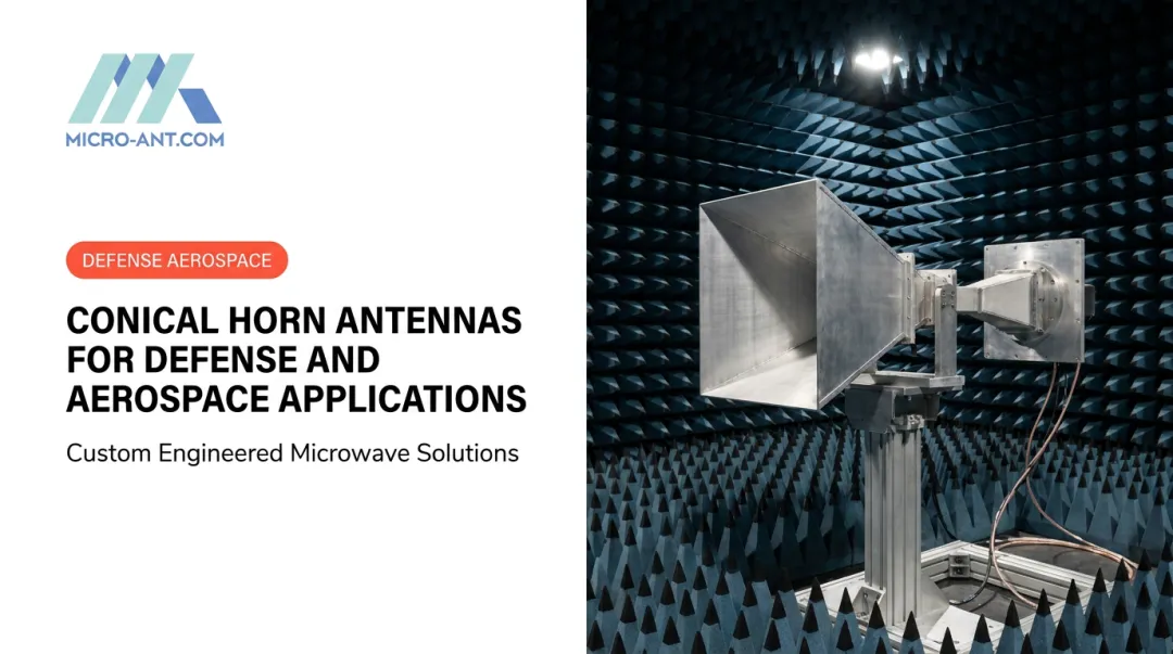
| Conical | Circular aperture with circular waveguide | Satellite feeds, radio astronomy, circular polarization applications |
| Sectoral (E/H-plane) | Flared in only one plane, fan-shaped beam | Search radar feeds requiring plane-specific coverage |
| Corrugated | Grooved walls control hybrid modes | SATCOM and EW feeds needing low cross-polarization |
| Ridged/double-ridged | Internal ridges extend bandwidth | Broadband EMC/EMI testing, SIGINT, counter-UAS sensing |
Pyramidal horns remain the workhorse for predictable, repeatable gain. Their rectangular geometry makes them a natural fit as standard-gain references in test ranges.
Unlike pyramidal designs, conical horns pair with circular waveguide, suiting satellite feed applications where pattern symmetry or circular polarization matters.
Where conical and pyramidal designs pursue symmetric patterns, sectoral horns trade two-plane control for deliberate fan-shaped illumination, useful when only one plane needs shaping.
Corrugated horns add manufacturing complexity but deliver the low cross-polarization and symmetric patterns that SATCOM reflector feeds demand (TICRA's corrugated horn design guidance).
Double-ridged horns sacrifice some pattern uniformity for instantaneous bandwidth, which is exactly what direction-finding, signal intercept, spectrum monitoring, and counter-UAS systems need.
Why Defense and Aerospace Programs Rely on Horn Antennas
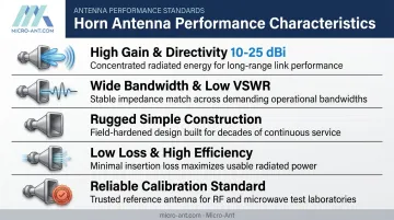
Horns didn't become the default RF sensor and feed choice by accident. Five performance characteristics keep them in fielded defense systems decades after Barrow's original design.
High gain and directivity. Standard-gain horn catalogs typically offer nominal 10, 15, or 20 dBi options, with some specialized models reaching 25 dBi in narrower bands, according to A.H. Systems' standard-gain horn antenna specifications. Higher gain concentrates energy into a narrower beam, which extends radar detection range and sharpens targeting precision.
Wide bandwidth and low VSWR. Horns lack resonant elements, so many designs operate cleanly across broad frequency ranges. That flexibility matters for multi-mission platforms that need to cover several bands without swapping hardware.
Rugged, simple construction. No moving parts, no tuning elements. That simplicity holds up under:
- Shock and vibration on airborne and ground-vehicle platforms
- Temperature extremes from high-altitude flight to desert ground operations
- Moisture and salt fog exposure on shipborne installations
Low loss and high efficiency. A well-designed horn preserves signal strength across long-range communication links and captures weak radar returns without adding unnecessary noise.
Reliable calibration standard. According to NIST's antenna calibration research, standard-gain horns generate known reference fields inside anechoic chambers for probe calibration work. That same predictability makes horns the go-to reference for EMC/EMI compliance testing.
Critical Applications in Defense, Aerospace, and Adjacent Sectors
Horn antennas show up wherever a program needs a dependable, high-gain RF interface.
- Radar and electronic warfare: Target acquisition, tracking, and missile guidance on airborne, shipborne, and ground platforms all lean on horn feeds or standalone horn sensors for their directional properties.
- SATCOM ground stations and terminals: Feed horns illuminate parabolic reflectors to deliver stable multi-band connectivity, with corrugated Ka/Ku-band feeds enabling roaming across multiple satellite operators as more constellations come online.
- Test and calibration ranges: Anechoic chambers and EMC/EMI test setups rely on standard-gain horns as stable, traceable references, since compliance measurements need a known-good standard to validate against.
These aren't isolated use cases. A single defense program might specify a corrugated Ka-band feed for its SATCOM terminal and a double-ridged horn for its EW sensor suite, both sourced to meet the same qualification bar.
Design and Performance Considerations for Mission-Critical Horn Antennas
Specifying a horn antenna for a defense program means balancing RF performance against physical and environmental constraints.
Flare angle and aperture tradeoffs. Wider apertures raise gain and narrow beamwidth, but they also add length and weight. Engineers work within platform envelope limits, often accepting a shorter, wider-flare design over a longer, narrower one when integration space is tight.
Environmental hardening. Materials selection drives survivability. Aluminum alloys and composites, paired with protective coatings, need to hold up against:
- Moisture ingress and salt fog on maritime platforms
- Vibration and shock loads during flight or transport
- Temperature swings from sub-zero altitude to desert ground heat
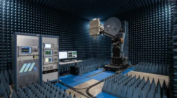
Verification through testing. RF performance claims mean nothing without measured data. Near-field and far-field chamber testing across the full operating band confirms gain, pattern, VSWR, and cross-polarization before a horn ever reaches the field.
In-house test facilities cut real time out of this process. Micro-Ant's spherical and planar near-field chambers, spanning 750 MHz to 40 GHz, mean qualification data doesn't wait on third-party lab scheduling.
A standard test cycle, covering fixturing, shipping, and measurement, runs on a four-week planning window, with both on-site witnessed and remote testing options available.
Partnering with a Trusted Horn Antenna Manufacturer
Off-the-shelf horn antennas work for generic applications. Defense and aerospace programs rarely fit that mold. Mission-specific frequency bands, tight envelope constraints, and platform-specific environmental profiles usually call for a design built around the actual requirement, not a catalog part adapted after the fact.
Micro-Ant has spent over 20 years engineering bespoke antenna systems for government, aviation, maritime, and land applications, including its award-winning Ultra-Wide Band Ka Antenna System and high-precision GNSS designs. That same custom-engineering approach applies to horn and feed component development across UHF through Ka-band.
A few things worth checking before committing to a manufacturing partner:
- Certifications: AS9100:2016 and ISO 9001:2015 confirm a quality management system built for aerospace and defense supply chains, though they don't substitute for measured RF performance data.
- CAGE code registration: A registered CAGE code (Micro-Ant's is 6XJFO) signals readiness for defense procurement processes.
- In-house test infrastructure: Near-field testing capability spanning 750 MHz to 40 GHz means faster, lower-risk qualification and quicker turnaround for program schedules that can't afford delays.

Vetting on these three points, rather than nominal gain numbers alone, gives program managers a clearer picture of whether a manufacturer can actually deliver against a defense-grade specification.
Frequently Asked Questions
What is a horn antenna used in a microwave?
A horn antenna transmits or receives microwave signals by flaring a waveguide into free space, smoothing the transition between guided and radiated energy. It's commonly used for radar systems and satellite feeds, plus lab calibration standards.
How does a microwave antenna work?
The horn's flare gradually matches the waveguide's impedance to free space, reducing reflected energy and VSWR. Aperture size and taper length then shape the radiated beam's gain and width.
What frequency range do horn antennas operate in?
Horn antennas commonly operate above roughly 300 MHz through microwave and millimeter-wave bands, with many designs supporting wide bandwidth ratios of 10:1 or greater within a single unit.
What is the typical gain of a horn antenna?
Standard-gain horns typically fall in the 10-20 dBi range, with specialized narrowband models reaching practical upper limits near 25 dBi. Exact gain depends on aperture size and operating band.
Why are horn antennas preferred for radar and satellite systems?
High directivity and low signal loss, paired with rugged, no-moving-parts construction, make horns dependable under the shock, vibration, and temperature extremes common to radar and SATCOM platforms.
How do I choose the right horn antenna manufacturer for a defense program?
Look for AS9100:2016 and ISO 9001:2015 certification, in-house near-field/far-field testing capability, and a track record of custom engineering rather than catalog-only offerings.