Many engineering teams still treat the radome as packaging, something to spec after the antenna design is frozen. That habit is expensive. A U.S. Army test found that a 0.030-inch strip of silicone tape shifted a 2.24 GHz patch antenna's resonance down to 2.22 GHz — a small dielectric addition, a measurable detuning event. Multiply that kind of error across a boresight-critical defense platform and the stakes climb fast.
This guide walks through the electromagnetic, mechanical, and testing principles that separate a radome that protects hardware from one that quietly wrecks performance.
Key Takeaways
- Match dielectric constant, thickness, and clearance to your operating wavelength.
- Choose wall construction and frequency classification based on actual bandwidth needs.
- Wind, ice, vibration, and water film affect performance as much as any model.
- Validate every design in an RF test chamber before fielding it.
What Is an Antenna Radome, and Why Does Its Design Matter?
A radome — short for radar dome — is a protective enclosure built around an antenna to shield it from wind, rain, ice, debris, vibration, and tampering. The name implies the goal: a structure that's mechanically tough but electromagnetically invisible.
That invisibility is possible because RF and radar signals pass through many non-metallic materials with minimal disruption. That's why radomes turn up in:
- Vehicle bumpers and vehicle roofs
- Aircraft nose cones
- Ship masts and superstructures
- Satellite terminal enclosures
Achieving that invisibility is only half the job. A poorly designed radome doesn't just add weight — it introduces reflection, attenuation, and pattern distortion that degrades receiver sensitivity or causes boresight error (the angular offset between where an antenna thinks it's pointing and where it actually is).
In defense, aerospace, and maritime systems, that error isn't cosmetic. It's the difference between a locked track and a missed one.
Electromagnetic Design Principles Every Radome Engineer Should Know
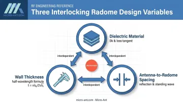
Radome electromagnetic design comes down to three interlocking variables: material, thickness, and spacing. Get one wrong and the other two can't fully compensate.
Selecting the Right Dielectric Material
Suitable radome materials must be non-metallic, dry, and free of carbon black or metallic particles in coatings and paints — any of these will reflect or absorb RF energy rather than transmit it.
Dielectric constant (Dk) drives how much of the signal reflects at the surface. Lower Dk generally means lower reflection loss:
| Material | Approximate Dk | Approximate tan δ |
|---|---|---|
| Structural foam | ~1.05 | 0.0015 at 10 GHz |
| Unfilled PTFE | ~2.05 | 0.0004 at 1–10 GHz |
| Polycarbonate | ~2.90 (drops toward 2.56 at 38.2 GHz) | 0.005 at 2.5 GHz |
| Fused quartz | ~3.78 | 0.0002 at 9.375 GHz |
According to Curbell Plastics' technical white paper on high-performance radome plastics, polycarbonate's Dk shifts meaningfully across frequency while PTFE stays comparatively stable.
That's the key lesson: don't trust a datasheet value measured at 100 MHz for a Ku- or Ka-band design. Loss tangent needs verification at the actual operating frequency, or the radome's real-world loss will surprise you.
Calculating Optimal Radome Thickness
The classic monolithic radome follows a half-wavelength matching rule. At normal incidence:
t = n × λ₀ / (2 × √εr)
Where t is physical thickness, n is an integer, λ₀ is the free-space wavelength, and εr is the material's relative permittivity. Because wavelength shortens inside a dielectric, the physical thickness needed is always less than a free-space half-wavelength.
Two things trip engineers up here:
- Incidence angle matters. A thickness that's reflectionless at normal incidence won't stay reflectionless across a scanned beam's full angle range.
- Manufacturing tolerance is application-specific. High-frequency programs may hold thickness to roughly 0.1 mm, while sandwich-core processes have historically used ±0.635 mm. Base tolerance on your RF sensitivity budget and fabrication capability, not a generic number.
Determining Antenna-to-Radome Distance
Energy reflected off the radome's inner surface can travel back to the antenna aperture and reradiate, creating a standing-wave effect that shows up as amplitude ripple in the pattern. Correctly tuned wall thickness relaxes how sensitive the system is to this gap, but it doesn't eliminate the need to check it.
Nearby dielectric material also perturbs the antenna's fringing fields and input impedance, which is one more reason gap spacing should be verified through actual pattern testing rather than assumed from a spacing formula alone.
Radome Types, Wall Styles & Geometry for Different Platforms
Once the electromagnetic fundamentals are set, the next question is construction: what frequency range needs to pass through, and what wall style gets it there efficiently.
Frequency-Based Radome Classifications
MIL-R-7705B, though formally cancelled in 1995 with no superseding document, remains the industry's common shorthand for radome frequency classes. The specification defines Types by bandwidth:
- Type I — low frequency, at or below 2.0 GHz
- Type III — narrowband, fractional bandwidth under 0.10
- Type V — broadband, fractional bandwidth 0.10 to 0.667
- Type VI — very broadband, above 0.667
Matching classification to your actual bandwidth need avoids two failure modes. One is over-engineering a narrowband application with a complex multi-layer wall; the other is under-engineering a broadband requirement with a wall that can't hold performance across the full band. That classification call also determines which wall construction can realistically deliver the performance you need.
Wall Construction: Monolithic vs. Sandwich vs. Multi-Layer
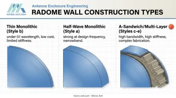
Three wall families cover most applications:
- Thin monolithic (Style b): Wall thickness under 0.1 wavelength. Simple, cost-effective, broadly transparent, but limited stiffness for large self-supporting structures.
- Half-wave monolithic (Style a): Strong and straightforward near its design frequency, but narrowband and sensitive to incidence angle.
- A-sandwich / multi-layer (Styles c–e): Higher-Dk skins around a lower-Dk foam core. Better bandwidth and structural stiffness, at the cost of more fabrication steps and tighter process control.
Cost tracks surface area closely, and surface area scales with the square of diameter — double a radome's diameter and you roughly quadruple the material and labor involved, before accounting for seams or reinforcement. Wall style, then, is as much a cost decision as an electromagnetic one. Once that construction is settled, the next variable is how individual panels are shaped and seamed together across the full structure.
Geometry & Panel Layout for Large Radomes
Large ground and shipboard radomes typically use quasi-random triangular, hexagonal, or pentagonal panel tessellation instead of uniform panel grids. Irregular geometry spreads out scattering effects instead of concentrating them at predictable frequencies where a uniform panel pattern would reinforce errors.
Joint design matters more than most engineers expect. Per CCI's radome white paper, a narrow, internally fastened perpendicular joint scatters roughly 8 times less energy than a parallel lap joint. Parallel laps also penetrate the RF surface, creating spots where dirt, moisture, and corrosion collect.
Platform-Specific Shape Considerations
Different platforms load the design problem differently:
- Aviation radomes balance aerodynamic drag and structural loads with RF transparency, often under nose-cone geometry constraints that leave little room to adjust wall thickness.
- Maritime and vehicle-mounted radomes contend with salt spray, humidity, and continuous vibration — conditions that punish coatings and seams faster than a lab environment ever would.
This is where Micro-Ant's work sits: engineering rugged, field-tested bespoke antenna enclosures for defense, aviation, and maritime deployments, where the radome has to survive the platform as much as protect the antenna inside it.
Mechanical & Environmental Design Considerations
Electromagnetic performance means little if the radome cracks, deflects, or floods with water in the field. Structural design has to account for site-specific wind loading, snow, and ice accumulation, and ASCE/SEI 7-22 is the current reference for minimum design loads, covering wind, atmospheric ice, and seismic conditions by location and risk category.
Manufacturer benchmarks commonly cited for sandwich-radome design include:
- 150 mph sustained wind loading
- 50 lb/ft² combined snow-and-ice loading
Actual requirements should always trace back to site hazard data, not a single generic number.
Static loads aren't the only mechanical stress worth planning for. Vibration is its own problem. Relative motion between the antenna and radome introduces phase errors that show up in coherent radar systems as micro-Doppler artifacts — signals that can mimic real target returns. Rigid mounting or mechanical damping is mandatory in high-vibration platforms to avoid chasing phantom detections.
Vibration isn't the only field hazard to design around. Water is the quiet performance killer. At 20 GHz, water's loss tangent runs close to 1.0, dramatically higher than any dry radome material discussed earlier. A thin water film on the surface behaves almost like a lossy antenna cover. That's why hydrophobic coatings matter:
- Cause water to bead and run off rather than sheet across the surface
- Reduce the loss contribution from rain and condensation
- Require validation under wet conditions, not just contact-angle measurement
Testing under simulated rain, not just dry insertion loss, is the only way to confirm a coating actually holds up at operating frequency.
Testing, Validation & Common Radome Design Mistakes
Every calculation above sets a baseline for performance. Real-world validation, through radiation pattern, boresight error, and insertion loss testing, confirms whether a radome actually performs as modeled.
Near-field RF test chambers make this practical. They measure a full antenna pattern with and without the radome in place, capturing gain loss, pattern distortion, sidelobe changes, and cross-polarization across frequency and scan angle.
Micro-Ant runs spherical and planar near-field chambers spanning 750 MHz to 40 GHz at its Jacksonville, Florida facility. This gives defense and satcom customers iterative testing cycles without the travel time and cost of shipping hardware overseas or to a third-party lab.

That same testing process often surfaces design mistakes that could have been caught earlier. Common radome mistakes worth flagging before they reach production:
- Painting or laminating directly over a patch antenna, which detunes its resonance, sometimes measurably, as the earlier silicone-tape example showed
- Using carbon-filled or metallic-pigmented coatings that absorb or reflect RF energy
- Ignoring manufacturing tolerance on wall thickness, assuming nominal dimensions will hold in production
- Uneven or non-parallel spacing between antenna and radome that goes unchecked until pattern testing reveals it
Catching these issues comes down to timing more than technology. Even when a radome problem does slip through, how a team responds still matters. As Micro-Ant President and Chief Scientist Charles McCarrick puts it:
"A company's character is defined by how they respond when things go terribly wrong. At Micro-Ant, we are committed to customer satisfaction, and we do not quit until that commitment is fulfilled."
Involving RF and structural engineers early in a platform's design cycle, before the antenna design is finalized, consistently produces better outcomes than retrofitting a radome onto a design that's already locked.
Frequently Asked Questions
What is the best material for an antenna radome?
Low-loss, non-metallic dielectrics such as PTFE, polycarbonate, or fiberglass composites are generally preferred. Final selection depends on frequency band, environmental exposure, and mechanical load requirements.
How thick should a radome be?
Radome thickness typically follows a half-wavelength (or integer multiple) rule based on the material's dielectric constant and the operating frequency. Exact thickness must account for incidence angle and manufacturing tolerance.
Does a radome reduce antenna range or signal strength?
A properly designed radome introduces minimal insertion loss. A poorly matched material, thickness, or antenna clearance, however, can measurably reduce range and distort the radiation pattern.
What's the difference between a radome and a standard equipment housing?
A radome is engineered specifically for RF transparency at the antenna's operating frequency. A generic equipment housing isn't optimized for electromagnetic performance and can degrade signal quality.
How do you test radome performance before production?
Near-field or far-field RF chamber testing measures pattern distortion, boresight error, and insertion loss across the full frequency band and scan range. These results confirm the design is ready before it's fielded.
Can a radome be added to an existing antenna without redesigning it?
Retrofitting is possible but risky. Distance, thickness, and material still need tuning to the antenna's existing frequency and pattern. Otherwise, performance will degrade in ways that are hard to trace after the fact.