At its simplest, a radar antenna converts electrical signals into electromagnetic waves, then converts the reflected waves back into electrical signals a system can interpret. That back-and-forth conversion is the entire foundation of radar detection, tracking, and guidance.
This guide breaks down how radar antennas work, the main antenna types defense and aerospace programs rely on, the specifications that define performance, and what to look for in an engineering partner for mission-critical programs.
Key Takeaways
- Radar antennas convert electrical signals into electromagnetic waves and back, forming every radar's core transmit/receive link.
- Reflector and phased array designs dominate defense radar, each suited to different mission profiles and platforms.
- AESA arrays anchor systems like the F-35's APG-81 and Navy's SPY-6, though PESA and mechanical designs remain in service.
- Frequency band, beamwidth, and polarization choices directly shape detection range, resolution, and clutter rejection.
- In-house testing and AS9100:2016 certification reduce schedule risk for custom antenna programs.
What Are Radar Antennas and How Do They Work?
A radar antenna is a microwave device that radiates electromagnetic energy outward or captures it from free space. The principle of reciprocity means the same antenna performs identically whether it's transmitting or receiving: its gain, pattern, and efficiency don't change based on the direction of signal flow. That's why a single aperture can send a pulse and, microseconds later, catch its own echo.
The Radar Operating Cycle
Every radar system follows the same basic loop:
- Transmit: a pulse of RF energy leaves the antenna and travels outward.
- Reflect: the pulse strikes a target (aircraft, missile, ship) and scatters energy back toward the source.
- Receive and analyze: the antenna captures the return, and the system measures timing, direction, frequency shift, and phase to calculate range, speed, and location.
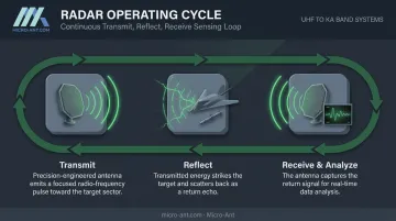
The antenna doesn't work alone. It sits at the transitional point between guided energy inside the system and free space beyond it, flanked by:
- Transmitter: generates the RF pulse
- Waveguide: channels energy to and from the antenna
- Duplexer: switches the antenna between transmit and receive modes
- Receiver: processes the returned echo
Gain, Directivity, and Radar Cross Section
Antenna gain measures how well an antenna concentrates energy into a focused beam instead of radiating it evenly in every direction (isotropically). Gain relates directly to aperture size and wavelength: a larger physical aperture at a given frequency produces a narrower, more powerful beam, extending detection range and improving pointing accuracy.
This is why nearly every modern defense and aerospace radar system uses a directional antenna rather than an omnidirectional design. Omnidirectional patterns cover all azimuths at once but can't resolve a target's exact bearing on their own. Directional, often pencil-beam, patterns concentrate energy for precise angular measurement, which targeting and tracking systems require.
Radar cross section (RCS) rounds out the picture. RCS measures how much energy an object reflects back toward the radar. A large commercial aircraft, for example, has a far bigger RCS than a fighter jet shaped to scatter energy away from the receiver. Because received power falls off with the fourth power of range, even small RCS reductions can meaningfully cut detection distance.
Types of Radar Antennas Used in Defense & Aerospace
Reflector Antennas (Parabolic & Cassegrain)
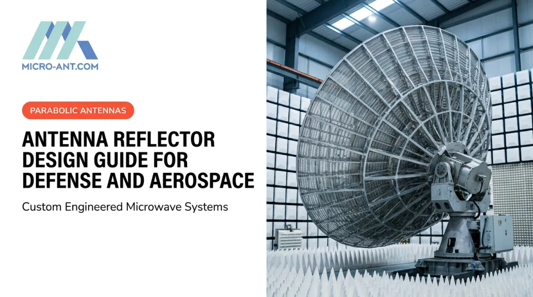
Parabolic "dish" antennas remain a workhorse design for long-range tracking radar. A feed antenna sits at the focal point, illuminating the dish surface so reflected energy leaves as a coherent plane wave. Engineers constantly balance illumination taper against spillover: over-illuminate the edge and energy leaks past the rim; under-illuminate it and usable aperture goes to waste.
Cassegrain configurations solve a related problem. A hyperbolic subreflector folds the RF path back toward the dish vertex, relocating the feed and its electronics to a more accessible, space-constrained position. This layout shows up in dual-frequency and long-range tracking radars, including documented C-band monopulse trackers, where packaging the feed near the vertex simplifies cooling and cabling.
Phased Array Antennas (Passive & Active Electronically Scanned Arrays)
Phased array antennas replace the single reflector with dozens or hundreds of radiating elements, each with individually controlled phase and amplitude. Adjusting phase relationships across the array steers the beam electronically, with no moving parts and no mechanical inertia to overcome.
Two architectures dominate:
- PESA (Passive Electronically Scanned Array): one centralized RF source feeds power through phase shifters to every element.
- AESA (Active Electronically Scanned Array): each element carries its own transmit/receive module, generating and receiving RF independently.
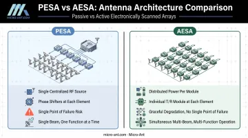
AESA has become the standard architecture for modern military aircraft and naval combat systems. Northrop Grumman's AN/APG-81 fire control radar, flying on the F-35, and the Navy's SPY-6 family both rely on distributed T/R modules.
That architecture supports simultaneous multi-function operation, tracking multiple targets while still scanning for new ones. It also degrades gracefully if individual modules fail, rather than taking down the whole radar.
Bespoke engineering extends this same distributed-module thinking into multi-band apertures. Micro-Ant's Ultra-Wide Band (3.5 GHz) Ka Antenna System and its Tri-Band Segmented Reflector and Feed technology, developed under the Kore Composites "Veritas" line, show how reflector and array-feed engineering can combine into a single aperture built for multiple frequency bands.
The UWB Ka system earned a "Most Innovative" award from the Satcoms Innovation Group, recognition that reflects the industry's growing demand for frequency-agile designs.
Specialized & Compact Radar Antennas
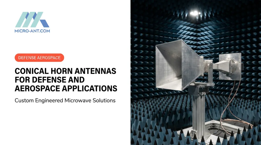
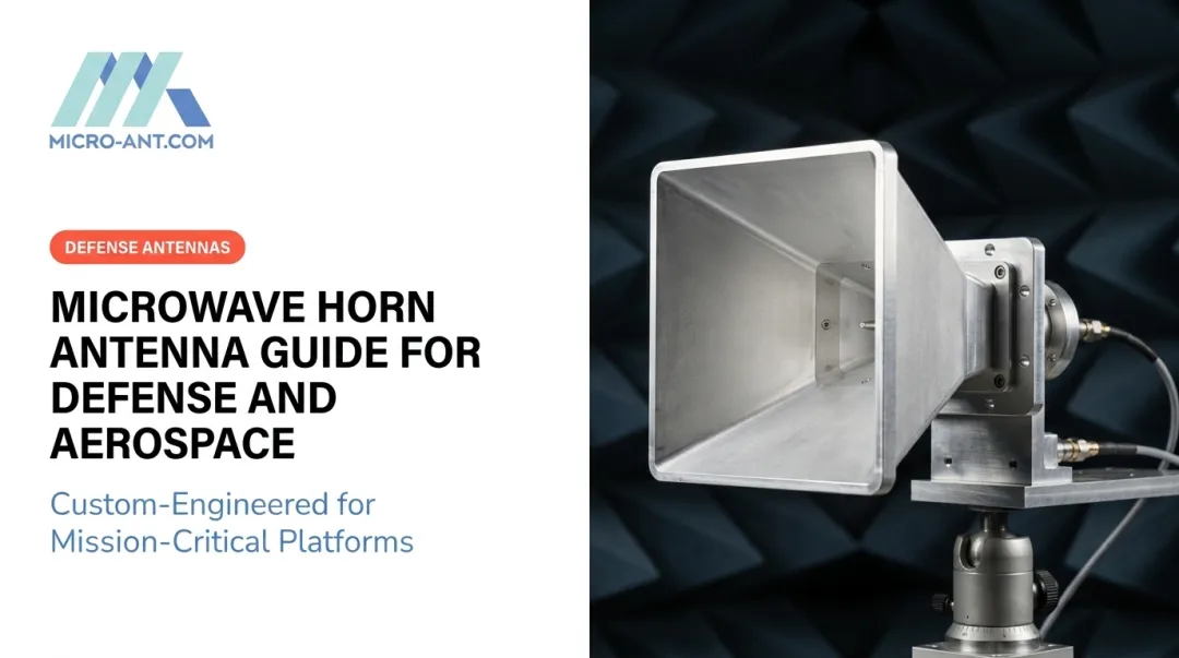
Not every application needs a large dish or array. Horn antennas offer a simple, compact design well suited to radar altimeters. A NASA pulse-compression altimeter program used a waveguide horn delivering roughly 21.6 dB gain from a 3.6-by-2.6-inch aperture. Slotted waveguide antennas serve shipborne and airport surface radar, favored for lower cost and reduced wind loading on exposed mounts.
Planar and Vivaldi-type antennas fill the wideband, high-directivity niche, appearing in ground-penetrating radar and ISR systems that need broad frequency coverage from a low-profile aperture.
Key Radar Antenna Specifications & Performance Parameters
Selecting a radar antenna starts with frequency. Defense and aerospace programs choose a band based on mission needs, and that choice cascades into every other design decision.
| Band | Range | Typical Defense/Aerospace Use |
|---|---|---|
| L/S-band | 1–4 GHz | Long-range surveillance, naval search radar |
| X-band | 8–12 GHz | Missile guidance, fire control, weather radar |
| Ku/K-band | 12–27 GHz | High-resolution imaging |
| Ka-band | 27–40 GHz | High-resolution mapping, SATCOM |
Beamwidth, Polarization, and Coverage Tradeoffs
Beamwidth and gain move in opposite directions. A larger aperture relative to wavelength produces a narrower beam and higher gain, improving tracking precision but shrinking the instantaneous coverage area. Programs constantly trade search coverage against pinpoint accuracy when sizing an aperture.
Polarization matters just as much:
- Circular polarization helps reduce rain clutter in same-sense configurations.
- Horizontal polarization performs differently against sea clutter depending on grazing angle and sea state.
- Vertical polarization offers no universal advantage either, so selection should be validated against the actual operating environment rather than a general rule.
Size, Weight, and Ruggedization
Airborne, shipborne, and ground-based platforms each impose different aperture constraints. A fighter jet's nose cone limits antenna diameter far more than a ship's mast or a fixed ground installation, pushing airborne AESA designs toward denser element packing rather than sheer size.
Defense-grade antennas also face environmental demands commercial designs rarely see:
- Extreme temperature swings, from arctic cold to desert heat
- Continuous vibration and shock loads on airborne and shipborne platforms
- Weatherproofing against salt spray, humidity, and precipitation
These conditions are exactly why bespoke, ruggedized engineering, rather than adapted commercial hardware, matters for mission-critical defense programs.
Why Do Radar Antennas Rotate or Scan?
Mechanical scanning remains one of the most cost-effective ways to build a 360-degree picture of the surrounding airspace or sea. A rotating antenna sweeps a narrow beam around the horizon, and the system plots each return onto a Plan Position Indicator (PPI) display, the classic circular radar screen. The E-3 Sentry's 30-foot rotodome completes a full rotation every 10 seconds while scanning out past 250 miles.
Three mechanical scan types cover most defense and aerospace needs:
- Circular scan: continuous 360-degree rotation for wide-area surveillance
- Sector scan: concentrates coverage on a bounded angular region for track-while-scan missile radar
- Conical scan: rotates an offset beam around boresight to derive precise tracking error
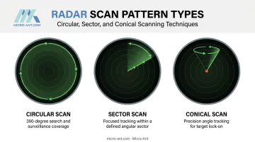
Electronic scanning, used in phased array systems, replaces physical rotation with phase adjustments across the array. There's no inertia to overcome and no motor to wait on, so the beam can jump between targets almost instantly.
This speed lets a single AESA radar track dozens of targets, scan for new threats, and support fire control simultaneously, a scheduling flexibility mechanical rotation can't match. Micro-Ant's phased array and beam-switching ESA antennas are engineered for exactly this kind of multi-target tracking mission.
Mechanical scanning still earns its place in cost-sensitive surveillance and marine radar, while electronic scanning wins out wherever multi-target tracking speed drives mission success.
Applications of Radar Antennas in Defense and Aerospace
Radar antennas show up wherever a defense or aerospace platform needs to detect, track, or communicate.
Missile defense and naval combat systems depend heavily on phased array antennas for simultaneous multi-target engagement. Aegis-type architectures use AN/SPY multifunction phased arrays capable of tracking more than 100 targets at once, according to the Navy.
The Army's Patriot and LTAMDS systems also rely on phased array tracking radars. LTAMDS adds three arrays for full 360-degree coverage, replacing the front-facing-only design of older Patriot radars.
Airborne radar applications span a wide range:
- ISR and airborne early warning platforms like the E-2D use combined mechanical and electronic scanning for persistent situational awareness
- Targeting radars on fighter aircraft rely on AESA apertures packed into tight nose-cone volumes
- Radar altimeters use compact horn antennas to measure precise height above terrain, feeding safety-critical systems
Satellite communications and GNSS-linked antenna systems round out the picture, supporting secure defense connectivity and precision navigation across multiple constellations. This is where Micro-Ant's work intersects with radar-adjacent defense infrastructure.
The company's antennas support customers across SATCOM operators including Intelsat, Inmarsat, Iridium, and Thuraya, alongside government programs like ARSTRAT. This connects the sensor data radar systems generate to the networks that move it.
Choosing the Right Radar Antenna Partner for Defense & Aerospace Programs
Radar and antenna procurement for defense programs isn't like buying commercial hardware off a shelf. Quality certifications, testing infrastructure, and engineering depth all directly affect program risk.
Certifications matter first. AS9100:2016 and ISO 9001:2015 establish the traceability and quality assurance processes defense procurement officers expect before awarding contracts. Micro-Ant holds both certifications at its Jacksonville, Florida facility.
In-house testing cuts schedule risk. Programs that ship antennas to a third-party lab for validation lose weeks to travel, scheduling, and shipping.
Micro-Ant operates spherical and planar near-field test chambers covering 750 MHz to 40 GHz in-house. This lets customers validate performance without the added time and cost of an outside facility.
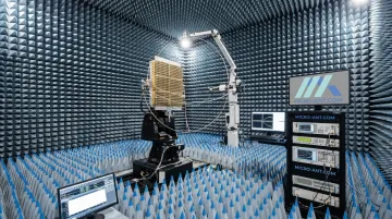
Bespoke engineering closes the gap between a standard catalog part and a mission-specific requirement. For more than two decades, Micro-Ant has delivered over a thousand custom antenna products across defense, aerospace, and satcom sectors.
That portfolio includes:
- Reflector systems and phased array antennas
- Beam-switching designs for adaptive coverage
- Airborne, maritime, and ground platform integrations
When evaluating a radar antenna partner, look for:
- Documented AS9100/ISO 9001 quality processes
- In-house, wide-frequency testing rather than outsourced validation
- A track record of custom, mission-specific designs, not just modified catalog products
- Domestic manufacturing for supply chain traceability
Frequently Asked Questions
What do radar antennas do?
Radar antennas transmit electromagnetic waves and receive their reflections. The system then detects, locates, and tracks objects based on the timing and characteristics of that returned signal.
What are the two types of radar antennas?
The two primary construction types are reflector antennas (parabolic or Cassegrain dishes) and phased array antennas, which use multiple elements to steer a beam electronically instead of moving a dish.
Why do radar antennas spin?
Rotation lets a narrow, high-gain beam sweep across a wide area for 360-degree surveillance. Modern phased array systems can scan electronically without any physical movement.
What is the frequency of a radar antenna?
Radar antennas operate anywhere from HF up through millimeter-wave bands. The specific frequency depends on required range, resolution, and mission, such as X-band for missile guidance or Ka-band for high-resolution mapping.
What is the difference between AESA and PESA radar antennas?
AESA gives every array element its own transmit/receive module, enabling multi-function operation and graceful degradation if a module fails. PESA relies on one centralized transmitter distributed across the array through phase shifters.
How are defense-grade radar antennas tested and certified?
Defense antennas are validated in near-field test chambers across their full operational frequency range, backed by AS9100 and ISO 9001 quality processes that document traceability before deployment.