Introduction
Smallsat launches keep climbing, but the physics of antenna design hasn't gotten any friendlier. In 2024 alone, 2,790 smallsats launched, accounting for 97% of all spacecraft and 81% of total upmass, according to BryceTech's Smallsats by the Numbers 2025 report.
That growth creates a real headache for RF engineers. A 1U CubeSat measures just 100 x 100 x 113.5 mm, yet a quarter-wave UHF element at 435 MHz needs roughly 172 mm to work properly.
Mission-critical links demand bigger apertures and higher gain. Launch providers demand smaller stowed volumes. Something has to give.
This guide breaks down the deployable antenna types solving that conflict, the engineering challenges they introduce, and what to look for when selecting a manufacturing partner.
Key Takeaways
- Deployable antennas expand aperture after launch, balancing stowage limits with in-orbit performance
- Wire, helical, mesh, and panel array designs each suit different frequency bands and missions
- A stuck or partial deployment can end a mission, making reliability the top risk
- Mounting near CubeSat bodies or solar panels shifts resonant frequency, requiring tight RF-mechanical coordination
- Partnering with a certified, experienced manufacturer cuts schedule and mission risk
What Are Deployable Antennas and Why CubeSats/Smallsats Need Them
CubeSats follow standardized form factors, from 1U (100 x 100 x 113.5 mm) up through 12U (226.3 x 226.3 x 366.0 mm). Every one of those dimensions is fixed by the launch dispenser, not by RF requirements.
That's a problem at lower frequencies, where quarter-wave elements dwarf the available bus space:
| Frequency Band | Quarter-Wave Length | Fits in 1U Bus? |
|---|---|---|
| VHF (145 MHz) | ~517 mm | No |
| UHF (435 MHz) | ~172 mm | No |
Neither fits inside a stowed 1U bus, forcing engineers to rethink antenna geometry entirely.
Deployable antennas solve this by physically extending, unfolding, or inflating after launch. The structure ships compact, then expands once clear of the fairing, achieving an electrical aperture the stowed envelope could never permit.
Compare that to low-profile alternatives like patch or PIFA antennas. These skip mechanical deployment entirely, which removes a failure point. But they sacrifice gain and range to do it, a tradeoff that only works for missions with modest link budget needs.
Deployables earn their complexity when missions require:
- High-resolution imagery downlink demanding wide bandwidth and strong signal margin
- Deep-space communication where every dB of gain extends mission range
- IoT constellations needing extended link budgets across dispersed ground terminals
Flight heritage backs this up. MarCO, ISARA, and RainCube all flew deployable X- or Ka-band reflectors on 3U-6U spacecraft, proving the concept works at scale smaller than most engineers assume possible.

Types of Deployable Antenna Technologies for Small Satellites
Not every mission needs the same aperture. Here's how the major deployable architectures break down by function and flight history.
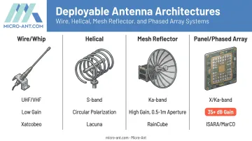
Wire and Whip Antennas (Monopole, Dipole, Yagi-Uda)
These are the workhorses of CubeSat TT&C. Spring-loaded or tape-spring mechanisms release thin metal elements that snap into position once a restraint (often a burn wire) is cut.
Xatcobeo, a 1U CubeSat, used four 170 mm steel-alloy strips held by a 0.25 mm nylon restraint that a resistance heater severed on command. Simple, low-cost, and mechanically straightforward.
That simplicity comes with a catch: every moving part is a potential failure point. Even so, wire-based designs can still scale up in performance. A Yagi-Uda variant tested at 435 MHz achieved 11.5 dBi gain with 53 MHz of bandwidth, proving these designs can push beyond basic omnidirectional coverage when higher gain is needed.
Helical Antennas
Foldable helix designs deliver circular polarization, which matters enormously when a satellite is tumbling or spin-stabilized. Linear polarization can null out entirely during certain orientations. Circular polarization keeps the link alive regardless of attitude.
Oxford Space Systems built a foldable helix that stowed inside a container roughly the size of a tuna can. It sprang out to full satellite-length after a 2020 launch on a 3U Lacuna IoT CubeSat, and it has operated in orbit ever since.
Mesh and Membrane Reflector Antennas
When missions need serious gain, mesh reflectors deliver. RainCube deployed a 0.5-meter Ka-band mesh reflector from a 6U bus and ran the first active radar instrument ever flown on a CubeSat, according to JPL's RainCube mission page.
NASA has also developed a 1-meter X/Ka-band mesh reflector compatible with a 12U bus for deep-space telecom applications. These designs unfold from a compact stowed package to an aperture spanning several times the spacecraft's own dimensions.
Deployable Panel and Phased Array Antennas
Flat-panel reflectarrays and emerging phased array designs are pushing data rates higher for Earth observation and broadband constellations.
ISARA, a 3U spacecraft, mounted a Ka-band reflectarray on the back of its solar array. NASA reports greater than 35 dB gain and a 100 Mbps design target, according to NASA's ISARA mission overview.
MarCO's tri-fold X-band reflectarray, measuring 59.7 x 33.5 cm, delivered 29.2 dBic gain and relayed real-time InSight landing data from Mars.
Active phased arrays remain mostly developmental for CubeSats, with proposed 4096-element Ka-band designs targeting future LEO constellations. They eliminate mechanical pointing but demand more DC power and thermal management than most small buses can currently spare.
Key Design and Engineering Challenges
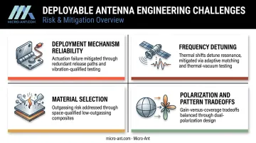
Deployable antennas introduce engineering problems that fixed antennas never face, and four issues stand out as the most critical to solve.
Deployment mechanism reliability tops the list. A stuck hinge or a failed burn wire can silence a mission permanently. Common actuation methods include:
- Burn-wire release, where current heats a nichrome element to sever a restraint
- Spring-loaded hinges that store elastic energy in tape springs or folded booms
- Shape-memory alloys that return to a programmed shape when heated
One nichrome release mechanism was tested through more than 400 firings in air and vacuum across temperatures from -50°C to +70°C. That's the level of repetition rigor deployment mechanisms need before anyone trusts them on orbit. Redundancy in the release path matters just as much as the mechanism itself.
Frequency detuning is the second major issue. Mounting an antenna against the CubeSat body or near solar panels changes the local electromagnetic environment, and nearby structure, hinges, cables, and deployed geometry all interact with the radiating element.
There's no universal correction number here. Every configuration needs integrated EM modeling and measured S-parameters in its final deployed state, not a generic assumption carried over from a previous program.
Material selection brings its own constraints:
- Outgassing must stay under TML ≤1.0% and CVCM ≤0.1% per ASTM E595 for anything nonmetallic
- Thermal cycling and radiation exposure must be verified against the mission's actual life cycle, not a blanket dose figure
- Mass and thickness stay minimal, often relying on thin aluminum sheet radiating elements
Finally, polarization and pattern tradeoffs force a real decision. TT&C links favor omnidirectional coverage for reliability regardless of attitude, while payload data downlink favors directional, high-gain patterns.
Few designs do both well. Early mechanical-RF co-design prevents costly redesigns late in the program, especially when it's aligned with the launch provider's vibration and shock standards from the start.
Testing and Qualification for Space Environments
Ground testing is where deployable antennas earn their flight certification. GSFC-STD-7000B (GEVS) doesn't mandate one universal test sequence. Instead, programs tailor levels and order to the mission, launch vehicle, and risk posture.
A typical qualification campaign includes:
- Thermal vacuum cycling to verify performance across the mission's expected temperature extremes
- Vibration and shock simulation matched to launch vehicle requirements, often at protoflight levels (limit +3 dB for one minute, per axis)
- Repeated deployment cycle testing to confirm the mechanism releases reliably, not just once
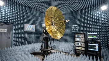
RF performance gets verified separately, through near-field or anechoic chamber testing across the antenna's full operational range. This confirms key metrics hold up post-deployment, not just on paper:
- Gain
- Radiation pattern
- Efficiency
Facilities with broadband testing capability matter here. Micro-Ant's in-house spherical and planar near-field chambers cover 750 MHz to 40 GHz. This range lets engineering teams validate a UHF TT&C antenna and a higher-frequency payload antenna in a single campaign, rather than shuttling hardware between separate labs.
Choosing the Right Deployable Antenna Partner for Your Mission
Selecting a manufacturer for deployable antenna hardware is a risk decision as much as a technical one. A few criteria separate reliable partners from risky ones:
- Flight heritage or comparable qualification rigor in space-adjacent applications, not just catalog experience
- Bespoke engineering capability, since most CubeSat missions need a design tailored to a specific bus, frequency, and mounting geometry rather than an off-the-shelf part
- Industry certifications like AS9100 and ISO 9001, which confirm process control, traceability, and consistent quality management even though they don't certify RF performance directly
Working with a US-based manufacturer carries practical advantages too. Rapid-turnaround testing without cross-border shipping cuts weeks off a qualification campaign and reduces the travel burden on engineering teams who need to be present for test reviews.
Micro-Ant brings over 20 years of bespoke antenna design and manufacturing experience to satcom, defense, and aerospace customers from its Jacksonville, Florida facility. The company holds those same certifications and operates in-house spherical and planar near-field test chambers spanning 750 MHz to 40 GHz. That range covers both UHF TT&C and higher-frequency payload bands in one location.
For engineering teams weighing deployable antenna options against a tight schedule, that combination of certified process control, custom engineering depth, and in-house RF verification should top your shortlist.
Frequently Asked Questions
What is a deployable antenna in satellite technology?
A deployable antenna is a structure that unfolds, extends, or inflates after launch to reach an operational size larger than its stowed launch configuration allows. This lets small satellites achieve apertures that wouldn't otherwise fit inside the launch dispenser.
What types of antennas are used on CubeSats?
Common types include monopole and dipole wire antennas, patch antennas, helical designs, and mesh reflectors. These operate across UHF, VHF, S-band, X-band, and Ka-band depending on whether the mission needs TT&C or high-rate payload downlink.
Why can't CubeSats just use fixed antennas instead of deployable ones?
Fixed, low-profile antennas like patches sacrifice gain and range to avoid deployment risk. When a mission needs stronger link margin or a larger aperture than the stowed bus permits, deployables become necessary.
How do deployable antennas actually unfold in space?
Common actuation methods include spring-loaded hinges that release stored elastic energy and burn-wire mechanisms that sever a restraint using heat. Shape-memory alloys are also used, returning to a programmed shape once heated.
What frequency bands do CubeSat antennas typically use?
UHF and VHF handle most TT&C links, while S-band, X-band, and Ka-band support higher-data-rate payload communication. NASA identifies UHF, S, X, and Ka among the typical smallsat communications bands.
How reliable are deployable antenna mechanisms on small satellites?
Reliability depends heavily on mechanism design, redundancy, and how thoroughly the hardware gets ground-tested before flight. Rigorous vibration, thermal, and repeated-cycle testing reduces the risk of an on-orbit deployment failure.