That bandwidth comes at a cost. Engineers designing 60 GHz phased arrays face problems that don't exist at S-band or even Ka-band: strong oxygen absorption, wavelengths near 5mm, manufacturing tolerances measured in microns, and feed networks that punish even small layout errors.
This guide walks through phased array fundamentals, the design parameters that matter most at 60 GHz, a practical simulation workflow, common pitfalls, and how working with an experienced antenna manufacturer can shorten the path from simulation to field-ready hardware.
Key Takeaways
- 60 GHz phased arrays steer beams electronically through phase control, with no moving parts
- Oxygen absorption limits range but enables interference-resistant, short-range links
- Element spacing, feed topology, and phase-matching accuracy drive array performance most
- Full-wave EM simulation (FDTD/MoM/FEM) is non-negotiable before fabrication at this frequency
- An experienced manufacturing partner reduces risk moving from simulation to production
What Is a 60 GHz Phased Array Antenna?
A phased array is an electronically scanned array (ESA) that steers a radio beam by adjusting the phase at each radiating element rather than physically moving the antenna. The concept isn't new: Karl Ferdinand Braun demonstrated the first directional phased array back in 1905, and the underlying math hasn't changed much since.
Why 60 GHz Is Different
At 60 GHz, the free-space wavelength is roughly 5mm. That small size lets designers pack dozens or hundreds of elements into a compact aperture, which is exactly why WiGig chips and 5G small cell panels can fit high-gain arrays into palm-sized enclosures.
The band also sits near a molecular oxygen absorption resonance. Under standard atmospheric conditions, ITU-R P.676 models attenuation near the peak at approximately 15 dB/km, though the exact figure shifts with pressure, humidity, and altitude. This naturally limits range but also reduces interference between nearby systems, a real advantage in dense deployments like conference rooms or data center racks where dozens of radios operate within feet of each other.
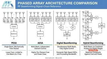
Four Architectures, Four Tradeoffs
| Architecture | Signal Path | Beam Capability | Main Tradeoff |
|---|---|---|---|
| PESA | Single RF chain, passive phase shifters | One steerable beam | Lower cost, single point of failure |
| AESA | Distributed active T/R modules | Fast scan, multiple beams possible | Higher complexity, better fault tolerance |
| Digital beamforming | Per-element conversion/weighting | Most simultaneous beams | Highest power and processing load |
| Hybrid beamforming | Analog subarrays + digital layer | Multiple streams, bounded by RF chains | Balances flexibility and cost |
Regardless of which architecture you choose, beam steering itself still comes down to array factor: elements spaced and phased so their wavefronts add constructively in the desired direction and cancel elsewhere. It's simple in principle, unforgiving in execution at millimeter scale.
You'll already find active 60 GHz arrays in commercial products today, from WiGig docking stations to multi-panel router and smartphone radios that use small phased subarrays for beam alignment.
Where 60 GHz Phased Arrays Are Used Today
WiGig and 802.11ad/ay remain the original commercial driver. IEEE 802.11ad supports data rates up to 7 Gb/s, enabling wireless docking and uncompressed video streaming without the cable clutter.
The same spectrum also scales to wide-area connectivity: 5G/6G mmWave and fixed wireless access rely on beamforming to close the link budget. Path loss climbs sharply above 30 GHz, so concentrating RF energy into a narrow, steerable beam is what makes small cell and FWA deployments viable at all.
Other emerging applications include:
- Short-range automotive and industrial radar, where compact beamwidth aids object detection
- Point-to-point backhaul links, where field trials have shown throughput near 1.1 Gb/s in a 250 MHz channel
- Satellite and inter-satellite links, where oxygen absorption becomes an asset for interference isolation once the signal leaves Earth's atmosphere
Each use case imposes different power, scan range, and regulatory constraints, so treat them as separate design problems rather than variations on one template.
Core Design Parameters for a 60 GHz Phased Array
Element Spacing and Grating Lobes
Standard practice keeps element spacing at half-wavelength, about 2.5mm at 60 GHz. Exceed that spacing and grating lobes appear, sending energy toward unwanted directions. Amplitude tapering across the array helps suppress sidelobes when tighter spacing is not achievable.
Feed Network Topology
Series-fed and parallel (corporate) feed networks trade off differently at mmWave:
| Feed Type | Strengths | Trade-offs |
|---|---|---|
| Series-fed | Fewer junctions, simpler routing | Accumulates phase and amplitude error along the chain |
| Parallel-fed (corporate) | Equal path lengths to every element | Consumes more board area, adds splitter loss |
Substrate Selection
Standard FR4 is not viable at 60 GHz. Its loss tangent and Dk variation are simply too high for millimeter-scale features. Low-loss laminates such as Rogers RO3003 or RO4000-series materials, and similar low-Dk/Df options, are the practical starting point. Their published loss figures at 10 GHz should not be assumed to hold at 60 GHz without direct characterization.
Phase-Matching and Feed Design
Larger arrays split across multiple sub-arrays or transceivers need careful feedline length tuning and reference clock distribution to keep phase error from creeping in between sections. Feed and excitation choices, whether waveguide or microstrip, also affect how much power actually reaches the radiating elements versus how much is lost in the transition.
Manufacturing Tolerance Sensitivity
This is where 60 GHz punishes complacency. A 5mm wavelength means sub-100-micron fabrication errors can measurably shift resonant frequency and degrade pattern performance. Standard PCB process tolerances hover around ±0.1mm, which is already a meaningful fraction of a critical dimension. Tolerance stack-up needs to be modeled, not assumed.
Simulating a 60 GHz Phased Array Before Fabrication
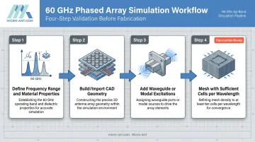
A disciplined simulation workflow catches problems while they're still cheap to fix.
- Define the frequency range and assign accurate material properties for copper conductors and the chosen low-loss dielectric
- Build or import CAD geometry, including feed structures and any packaging or connector transitions
- Add waveguide or modal excitations that match the intended feed mechanism
- Mesh with sufficient cells per wavelength: coarse meshing at mmWave produces misleading results fast
Full-wave solvers do the heavy lifting here. FDTD, MoM, and FEM-based tools (think HFSS, CST Studio Suite, or Keysight's planar EM workflows) predict S-parameters, gain, and 2D/3D radiation patterns before anything gets fabricated.
Array Synthesis Without Re-Simulating Everything
Rather than re-running a full simulation for every phase combination, engineers typically simulate a single element or an embedded element within a small subarray. They then apply superposition, combining weighted element patterns to predict full-array beam steering across the scan volume.
This approach is efficient, but critical scan states still deserve validation against a finite-array model. Isolated-element results can miss edge effects and mutual coupling that only appear once elements interact.
Far-zone and near-field sensors then confirm sidelobe levels, gain, and beam steering range match expectations across the intended scan sector.
This upfront validation is what makes simulation-first design pay for itself. Physical prototyping and mmWave-rated test equipment, such as VNAs and calibrated chambers, are expensive and slow to schedule.
Catching a spacing or feed error in simulation costs far less than discovering it after fabrication. Once results look solid, validate them against measured data from a near-field or spherical test chamber before committing to full production.
Common Challenges When Designing 60 GHz Arrays
Grating lobes from improper spacing remain one of the most frequent mistakes. The fix is straightforward in theory (respect the half-wavelength rule, apply amplitude tapering) but easy to get wrong when packaging constraints push spacing wider than ideal.
Feedline and connector losses matter far more at mmWave than at lower bands. A loss figure that seems negligible at 2.4 GHz can eat a meaningful chunk of your link budget at 60 GHz.
Published on-chip planar line losses run around 0.6 dB/mm, while lower-loss waveguide-style interconnects can drop below 0.05 dB/mm—the technology choice alone can make or break your link budget.
Thermal and power handling become real constraints in dense active arrays. Packing T/R modules tightly for gain and beamwidth also concentrates heat generation, and closely spaced modules have less surface area per element to dissipate it.
Partnering With an Experienced Antenna Manufacturer
Moving a 60 GHz phased array from a clean simulation to manufacturable, field-ready hardware is where many programs stumble. Simulation assumptions rarely survive contact with real fabrication tolerances, connector losses, and thermal realities without some adjustment.
This is where a manufacturing partner with deep phased array and precision fabrication experience earns its keep. Micro-Ant has spent over 20 years designing and manufacturing custom antennas across UHF through Ka-band, including electronically steered arrays for shipboard and aviation platforms. That experience translates directly into the discipline mmWave arrays demand:
- Tight tolerance control across machined and plated components
- Phase-matched feed networks for consistent beam performance
- Rigorous validation testing before hardware reaches the field
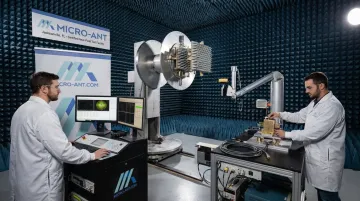
Micro-Ant's Jacksonville, Florida facility operates under AS9100:2016 and ISO 9001:2015 certification, with in-house spherical and planar near-field testing spanning 750 MHz to 40 GHz. That infrastructure supports the kind of rigorous pattern and gain validation that any high-frequency custom array design needs before it reaches the field.
If you're pushing into 60 GHz or other demanding mmWave and Ka-band territory, loop in antenna engineering expertise early. Aligning simulation assumptions with manufacturable tolerances up front avoids the redesign cycles that consume budget and schedule later.
Frequently Asked Questions
What frequency range is considered 60 GHz mmWave, and why is it unlicensed in many countries?
The 60 GHz band generally spans 57-71 GHz. In the US it's unlicensed under FCC Part 15, and the EU harmonizes the same range under CEPT rules. Regulators worldwide favor the band because oxygen absorption naturally limits interference range.
Why does oxygen absorb signals so strongly at 60 GHz?
Molecular oxygen has a resonance band near 60 GHz where multiple absorption lines merge under atmospheric pressure. This causes signal energy to attenuate steadily with distance, peaking near 15 dB/km under standard conditions.
What is the difference between a phased array and a traditional fixed antenna array?
A fixed array radiates a set pattern that can't change without physically repositioning the antenna. A phased array uses phase shifters at each element to steer the beam electronically, with no moving parts required.
How many antenna elements are typically needed in a 60 GHz phased array?
Compact devices like WiGig terminals often use 4-8 elements, while high-directivity systems can scale to dozens or even hundreds of elements. Element count depends on the gain and beamwidth your application requires.
What software tools are commonly used to simulate 60 GHz phased arrays?
Full-wave EM solvers like Ansys HFSS, CST Studio Suite, and Keysight's planar EM tools are standard. They use FDTD, MoM, or FEM methods to predict S-parameters, far-field patterns, and array steering performance.
Can 60 GHz phased arrays be used for long-range communication?
Not typically. Atmospheric oxygen absorption limits practical range to short and medium distances, making the band far better suited to high-throughput links like WiGig than long-haul communication.