Key Takeaways
- Acoustic and RF anechoic chambers serve entirely different purposes—selecting the wrong type invalidates your test program
- Match chamber selection to device type, frequency range, and the governing regulatory standard
- Three standards frameworks drive most programs: MIL-STD-461, CISPR 16-1-4, and ISO 3745
- Near-field chambers deliver accurate far-field data in a fraction of the physical space required by true far-field facilities
- Program-defensible data requires a chamber with current, traceable certification
What Is an Anechoic Chamber?
An anechoic chamber is a specially engineered room designed to eliminate reflections of sound or electromagnetic waves. Only the direct signal—not reflected energy—reaches the detector or antenna under test. This simulates free-field conditions that don't exist in ordinary rooms or outdoor test sites.
The concept traces back to acoustician Leo Beranek, who developed early anechoic environments during World War II-era research at Harvard. Originally limited to acoustic testing, the design later extended to radio-frequency (RF) chambers as defense and wireless testing demands grew.
Both acoustic and RF chambers share the same physical principle: absorptive materials lining the interior surfaces convert incident wave energy into heat rather than reflecting it back. The distinction lies in which materials are used and what governing standards apply.
Types of Anechoic Chambers
Acoustic Anechoic Chambers
Acoustic chambers use dense foam or fiberglass wedges on all interior surfaces to absorb sound energy. Applications include testing loudspeakers, microphones, HVAC components, and industrial noise emissions. NIST's acoustic anechoic chamber achieves ≥99% sound absorption above 45 Hz, with a characterized frequency range of 40 Hz to 63 kHz and an ambient A-weighted SPL below -2 dB.
Two configurations exist:
- Full anechoic chambers — all six surfaces treated, including the floor beneath a wire mesh grating with absorbers pointing upward; used for precision measurements requiring a true free field
- Hemi-anechoic (semi-anechoic) chambers — solid reflective floor retained, walls and ceiling treated; suited for heavy equipment like vehicles and machinery that cannot be suspended above floor absorbers
ISO 3745:2012 governs precision sound power measurements in full and hemi-anechoic rooms. ISO 3744:2025 covers sound power measurements using a reflecting plane—the hemi-anechoic configuration.
RF and EMC Anechoic Chambers
RF anechoic chambers replace foam with radiation-absorbent material (RAM) and are built inside a Faraday-cage-style shielded enclosure. The shielding serves two functions: preventing external interference from corrupting measurements, and containing emissions during high-power immunity tests. MIL-STD-461 specifies that shielded enclosures must maintain ambient electromagnetic levels at least 6 dB below the specified test limits.
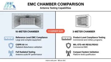
Two primary size categories define EMC chamber selection:
| Chamber Size | Primary Use | Standard Context |
|---|---|---|
| 10-meter | Reference-level EMC compliance for large/complex equipment | CISPR 16-1-4 radiated disturbance validation |
| 3-meter | Product-level compliance testing | MIL-STD-461 RE102/RS103; commercial EMC |
Near-Field vs. Far-Field Test Chambers
Far-field chambers place the antenna under test at a distance sufficient for the wavefront to be essentially planar. The required spacing follows the Fraunhofer criterion: R ≥ 2D²/λ, where D is the antenna's largest dimension and λ is the wavelength. For large-aperture or low-frequency antennas, that distance quickly becomes physically impractical.
Near-field chambers instead measure electromagnetic fields close to the antenna and apply near-field-to-far-field (NF/FF) mathematical transformations to derive far-field radiation patterns. IEEE Std 1720-2012 covers recommended practice for near-field measurements across planar, cylindrical, and spherical scanning geometries.
Each approach has distinct trade-offs worth considering:
- Far-field chambers require large physical distances — often impractical for low-frequency or large-aperture antennas
- Near-field chambers extract equivalent far-field data mathematically, enabling accurate results from a much smaller facility footprint
- Published operating ranges at high-performance near-field facilities span 400 MHz to 40 GHz, with some specialized systems reaching 140 GHz
How Anechoic Chambers Are Constructed
The Room-Within-a-Room Approach
The inner chamber is physically decoupled from the surrounding building structure, typically mounted on spring isolators or rubber pads. This prevents low-frequency vibrations—from foot traffic, HVAC systems, or road traffic—from propagating through the foundation into the test space. For RF chambers, the shielded outer shell provides the electromagnetic isolation layer.
Absorber Materials and Geometry
Pyramidal and wedge-shaped absorbers work by forcing incident waves to bounce repeatedly between adjacent pyramid faces, losing energy to the absorptive substrate on each interaction. The design rule: absorber depth must be approximately one-quarter wavelength at the lowest frequency to be absorbed. A chamber designed for 100 MHz requires far taller absorbers than one designed for 10 GHz.
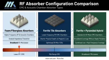
Two dominant absorber types serve different frequency ranges:
- Foam/fiberglass absorbers — used in acoustic chambers and RF chambers at higher frequencies; provide gradual impedance transition from free space to the absorptive substrate
- Ferrite tile absorbers — the primary solution for lower-frequency RF/EMC chambers; rely on magnetic loss properties to absorb high-frequency AC fields efficiently at shorter physical depths
Combining both materials, ferrite-plus-pyramidal hybrid designs are now standard in 10-meter EMC chambers—delivering broadband coverage without the physical depth penalties of foam-only configurations.
Floor Design Considerations
Floor construction differs between chamber types. Full anechoic chambers use a suspended wire mesh or steel grating floor, with absorbers mounted beneath it pointing upward to eliminate ground reflections entirely. Hemi-anechoic chambers retain a solid, reflective floor—intentionally, because it replicates the ground plane present during actual operation of vehicles and heavy machinery.
Key Standards Governing Anechoic Chamber Testing
Getting the standard right matters as much as getting the chamber right. Test data is only program-defensible if the chamber meets the applicable standard and that certification is current.
MIL-STD-461 specifies EMC requirements and test methods for U.S. Department of Defense electronics. Anechoic chambers lined with RAM inside shielded enclosures are the required test environment for radiated emissions (RE102) and radiated susceptibility (RS103) tests. Compliance is mandatory for equipment entering DoD programs.
Note: MIL-STD-461G is the widely referenced PDF revision dated December 2015, but ASSIST records show an active document date of April 2026. Verify the current revision through ASSIST before citing it in program documentation.
CISPR 16-1-4:2025 is the current IEC standard defining antennas and test sites for radiated disturbance measurements. For commercial EMC site validation, normalized site attenuation (NSA) must fall within ±4 dB of theoretical values across the 30 MHz to 1 GHz band.
For multimedia equipment emissions, CISPR 32:2015+A1:2019 is the applicable reference. CISPR 22 was superseded by CISPR 32 in 2015 and is no longer valid for new compliance submissions.
ISO 3745:2012 (with Amendment 1:2017) governs acoustic anechoic and hemi-anechoic rooms, specifying qualification procedures for free-field environments used in sound power measurements. Room performance checks are required after absorber modification and periodically at intervals not exceeding five years.
Once built, a chamber must pass acceptance testing against the applicable standard before a compliance certificate is issued. Test results generated in an expired or improperly commissioned chamber carry no regulatory weight.
Applications Across Industries
Defense and Aerospace
RF anechoic chambers are central to defense and aerospace testing programs:
- Radar cross-section (RCS) measurements for stealth platform characterization
- Antenna radiation pattern verification for airborne and shipboard systems
- EMC compliance testing under MIL-STD-461 for avionics, weapons systems, and ground vehicles
The Benefield Anechoic Facility (BAF) at Edwards Air Force Base is the largest known anechoic test facility in the world—its main chamber measures 264 ft × 250 ft × 70 ft and includes a 175-ton turntable capable of positioning fighter-sized aircraft. BAF supports antenna measurements from 100 MHz to 50 GHz and has hosted F-22 and Global Hawk EMI/EMC programs.
Commercial, Automotive, and Satellite Communications
Anechoic chambers also support a broad range of commercial applications:
- Consumer electronics — FCC and CE compliance testing before market release
- Automotive — hemi-anechoic chambers measure interior and exterior vehicle noise; full-vehicle antenna testing verifies GPS, cellular, and V2X performance in controlled RF environments
- Satellite communications — phased-array antennas, GNSS receivers, and multi-band terminals are verified against satellite operator certification requirements before deployment
The over-the-air (OTA) testing market reflects this expanding demand. MarketsandMarkets projects the OTA testing market to grow from $2.23 billion in 2024 to $3.17 billion by 2029 at a 7.3% CAGR, driven by 5G millimeter-wave devices, MIMO systems, and IoT modules requiring validation across wider frequency bands.

Antenna Testing in Anechoic Chambers
What Gets Measured
A properly equipped RF anechoic chamber enables measurement of the parameters that define antenna performance:
- Radiation pattern (gain vs. azimuth and elevation)
- Peak gain
- Axial ratio (for circularly polarized antennas)
- Half-power beamwidth
- Front-to-back ratio
- Port-to-port isolation in multi-band designs
All of these require a reflection-free environment. A single stray reflection can corrupt gain measurements or mask sidelobe behavior, errors that only surface after deployment when rework costs are high.
Near-Field Chambers for High-Frequency Programs
For Ka-band satellite terminals, GNSS systems, and phased-array platforms, near-field spherical and planar scanning chambers provide accurate far-field equivalent data without requiring the enormous physical distances that true far-field measurement demands. The NF/FF transformation produces the same radiation pattern data at a fraction of the facility footprint.
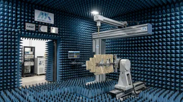
Micro-Ant's near-field testing facility in Jacksonville, Florida runs a spherical near-field scanner covering 750 MHz to 40 GHz in a 34'×24'×16' fully enclosed anechoic chamber, plus a planar near-field scanner covering 6 GHz to 40 GHz. Both systems accommodate antennas up to 2 meters in size.
Every antenna Micro-Ant manufactures goes through this facility before shipment, including Ka-band flat panels certified for Inmarsat and Ultra-Wide Band Ka systems validated for ARSTRAT. AS9100:2016 and ISO 9001:2015 certified processes ensure traceability and repeatability across every test result.
Why Facility Certification Matters for Program Compliance
Test data from an uncertified or improperly commissioned chamber may not be accepted by DoD customers, the FAA, or EASA. Before committing test resources to any facility, confirm its certification is current and applicable to your program. Key compliance checkpoints include:
- Defense programs: Alignment with MIL-STD-461 shielded enclosure requirements and IEEE antenna measurement practices
- Satellite operator certifications: Test reports traceable to a documented quality management system
- Aviation programs: Facility acceptance by FAA or EASA for the relevant test standard
Frequently Asked Questions
What is the difference between an acoustic and an RF anechoic chamber?
Acoustic chambers use foam or fiberglass wedge absorbers to eliminate sound reflections for audio and industrial noise testing. RF chambers use radiation-absorbent material (RAM) inside a Faraday-shielded enclosure to eliminate electromagnetic reflections for antenna and EMC testing. Different materials, different physics, different applicable standards—the two types are not interchangeable.
What standards apply to RF anechoic chamber testing?
Primary standards include MIL-STD-461 for defense electronics EMC, CISPR 16-1-4 and CISPR 32 for commercial EMC, and IEEE Std 149-2021 and IEEE Std 1720-2012 for antenna measurements. Compliance is verified through NSA testing or SVSWR site validation, with results documented in a commissioning certificate that must remain current.
How long can a person stay in an anechoic chamber?
There is no strict medical time limit, but most people find the experience disorienting within minutes. The absence of reflected sound removes the spatial cues the brain relies on for orientation, triggering discomfort, dizziness, or nausea. Most personnel limit exposure to under 30 minutes.
Why is it so hard to stay in an anechoic chamber?
The human auditory system relies on subtle echoes and ambient reflections for spatial orientation. When those reflections disappear, the brain loses a key input. In their absence, hearing becomes hypersensitive—as the BBC reports from Orfield Laboratories, people can hear their own heartbeat, blood flow, and breathing, sounds normally masked by ambient noise. The experience quickly becomes psychologically uncomfortable.
Can I visit an anechoic chamber?
Orfield Laboratories—which holds a Guinness record for quietest place—accepts visitors by appointment; some universities also offer scheduled demonstrations. Access to defense-related or commercially sensitive test chambers is restricted to authorized personnel.
What frequency range can anechoic chambers test?
Acoustic chambers typically absorb frequencies down to 50–100 Hz depending on wedge depth (NIST's chamber is characterized down to 40 Hz). RF chambers range from as low as 30 MHz for large 10-meter EMC chambers up to 40 GHz or higher for compact near-field systems—the low-frequency cutoff is set by absorber depth relative to wavelength.