Introduction
Walk past any telecom tower, satellite farm, naval vessel, or remote relay station and you'll spot them: dish-shaped antennas pointed at the sky or aimed across the horizon. These are parabolic microwave antennas, among the most recognizable RF hardware still in use today.
A parabolic microwave antenna is a reflector-based antenna that concentrates radio waves at microwave frequencies into a tight, high-gain beam. Get the type wrong, and you risk poor signal strength, wasted budget, or a system that can't scale with future demands.
This guide covers what these antennas are, why they matter, the four main feed configurations, and how to choose the right one for your project.
Key Takeaways
- A curved reflector focuses microwave signals (1-100+ GHz) into a narrow, high-gain beam
- This is foundational technology for satcom, backhaul links, radar, and radio astronomy
- Four types exist: prime focus, Cassegrain, Gregorian, and offset-fed, each with distinct trade-offs
- The right choice depends on frequency, gain, and size limits, not which design sounds most advanced
- Bespoke engineering and near-field testing turn paper designs into reliable field performance
What Is a Parabolic Microwave Antenna?
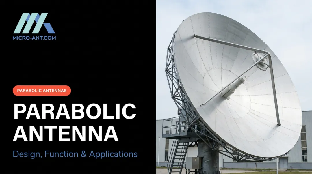
A parabolic microwave antenna is a reflector shaped like a parabola, paired with a feed positioned to send or receive microwave signals that the curved surface focuses into a beam.
Here's the working principle in plain terms: a feed placed at or near the focal point radiates a spherical wavefront outward. The parabolic reflector's geometry converts that wavefront into a parallel, collimated beam pointed along the antenna's axis.
This works because every path length from the focus, to the reflector surface, to a common plane in front of the dish is mathematically equal, a property unique to the parabola's curve.
From Handheld to Deep Space
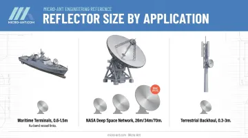
These aren't just theoretical shapes. Reflector size varies enormously depending on application:
- Small maritime terminals typically run 0.6 to 1.5 meters for Ku-band vessel links, according to ITU-R documentation on shipboard earth stations
- NASA's Deep Space Network operates 26 m, 34 m, and 70 m antennas, with a 70 m dish at every DSN site as the network's largest and most sensitive design, per NASA's DSN antenna overview
- Terrestrial point-to-point links commonly use 0.3 to 3 meter dishes for microwave backhaul between towers, balancing gain against wind loading and mounting constraints
Most of these systems operate within standard IEEE microwave bands: C (4-8 GHz), X (8-12 GHz), Ku (12-18 GHz), K (18-27 GHz), and Ka (27-40 GHz). Each band trades off differently between rain sensitivity, available bandwidth, and hardware size.
Why Are Parabolic Microwave Antennas Important?
Parabolic reflectors matter because of one property: directivity. By concentrating almost all transmitted energy into a narrow beam, they enable long-distance, point-to-point links that omnidirectional antennas simply cannot achieve, whether that's a telecom backhaul hop or a satellite uplink spanning thousands of miles.
That directivity is governed by physics: size and performance are directly linked. JPL's DESCANSO reference defines gain as G = 4πAe/λ², where Ae is the effective aperture area. For a circular reflector, this becomes G = ηₐ(πD/λ)², meaning gain scales with the square of the diameter, weighted by realized aperture efficiency (JPL, Large Antennas of the Deep Space Network).
What happens without a properly designed reflector?
- Weaker signal margins across the link
- Higher susceptibility to interference
- Larger power requirements to compensate for lost gain
- Shorter usable range before the signal degrades below threshold
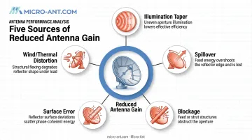
Real-world efficiency losses stem from several factors:
- Illumination taper across the aperture
- Spillover past the reflector edge
- Blockage from feed structures or struts
- Surface error from manufacturing tolerances
- Wind loading and thermal distortion of the dish itself
Micro-Ant's engineers factor in each of these when machining custom composite reflectors, since fractions of a millimeter in surface error can measurably cut gain. That's why, despite the rise of phased-array alternatives with electronic scanning, parabolic reflectors remain the default choice across defense, satcom, and radar work. Phased arrays offer flexible beam steering, but reflector-based systems still deliver higher single-beam gain at lower cost for many fixed-link applications.
Types of Parabolic Microwave Antennas
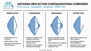
Parabolic antennas are classified primarily by feed geometry, meaning how the feed is positioned relative to the reflector. This geometry, not just the dish shape, determines aperture blockage, achievable efficiency, and which frequency bands and applications the design suits best.
You'll also see antennas classified by reflector shape, such as standard paraboloids versus cylindrical or shaped-beam radar reflectors. But for choosing a system, feed-based classification is what matters most. Four configurations dominate the field.
Prime Focus (Front-Fed/Axial) Antenna
This is the simplest configuration: the feed antenna hangs directly in front of the dish at its focal point, aimed back toward the reflector surface.
Core distinguishing factor: a single reflector with the feed sitting directly in the beam path.
Prime focus designs suit general-purpose links, smaller VSAT terminals, and cost-sensitive installations. It's the design most commonly used for simple point-to-point microwave links.
Strengths and limitations:
- Simplicity: fewer parts, easier to manufacture and maintain
- Lower cost than dual-reflector alternatives
- Main drawback: the feed structure physically blocks part of the beam, capping efficiency and increasing sidelobe levels
Cassegrain Antenna
Cassegrain designs use two reflectors. The primary feed sits at or behind the main dish and illuminates a convex hyperboloidal sub-reflector positioned near the focus, which redirects energy down to the main dish.
What sets it apart: moving the feed and its electronics out of the direct beam path, which allows bulkier low-noise amplifiers and RF front-end hardware to be mounted behind the dish rather than suspended in front of it.
This matters for large satellite communication ground stations, radio telescopes, and defense systems, where the receiver electronics are often too heavy or too complex to hang at the focal point. Micro-Ant's engineering team regularly designs reflector and feed systems for satcom and government customers who need this kind of configuration flexibility.
Benefits and trade-offs:
- Reduced spillover compared to simpler feeds
- Higher aperture efficiency achievable through careful sub-reflector shaping
- Trade-off: more complex fabrication and alignment, and generally higher cost than prime focus
JPL's DSN measurements illustrate how much design specifics matter here. Their 34 m reflex-feed Cassegrain antennas calculated 65.72% efficiency at S-band and 55.87% at X-band, while the 70 m DSS-14 antenna measured about 70% peak efficiency at its optimal rigging elevation.
These numbers show efficiency depends on the specific design and frequency, not a fixed value for "Cassegrain" as a category.
Gregorian Antenna
Gregorian antennas look similar to Cassegrain at first glance, but the sub-reflector geometry is different: concave and ellipsoidal instead of convex and hyperboloidal.
Key differentiator: the concave sub-reflector shape, which changes how energy is redirected to the main dish and can push efficiency higher in well-optimized designs.
This configuration suits high-performance radio telescopes and precision satcom or scientific applications where maximum gain and tight sidelobe control justify the added mechanical complexity. MeerKAT, for instance, uses an offset-Gregorian layout specifically because the off-axis geometry removes feed-support struts from the signal path entirely.
Strengths and limitations:
- Excellent sidelobe control, particularly in offset variants
- Very high efficiency potential — one proposed shaped offset-Gregorian design for the ngVLA project reported roughly 95% aperture efficiency, though that's a specific engineering result, not a category-wide average
- Trade-off: larger sub-reflector structures and tighter manufacturing tolerances than Cassegrain
Offset-Fed Antenna
Offset-fed antennas use an asymmetrical segment of a paraboloid, with the feed positioned to one side of the dish instead of directly in front of it.
Defining characteristic: the feed and its supporting structure sit completely outside the beam path.
This design is common in small dishes, home and commercial satellite TV, and compact VSAT terminals, where any centered feed blockage would meaningfully cut into performance on an already-small aperture.
ITU-R documentation confirms offset-fed antennas are widely used for VSAT operation and shows notably lower sidelobe levels than center-fed systems on 1.2-2.4 meter apertures, since there's no central obstruction scattering energy (ITU-R S.727-2).
Advantages and drawbacks:
- No aperture blockage, resulting in a cleaner radiation pattern
- Particularly effective at small apertures where blockage would otherwise dominate losses
- Trade-off: the asymmetrical shape is harder to mount and align, and becomes less practical at very large dish sizes
How to Choose the Right Type of Parabolic Microwave Antenna
The right type depends on your application's frequency band, required gain, size and weight constraints, and deployment environment. It has nothing to do with which design sounds the most sophisticated on paper.
Factors to Consider
Work through these before settling on a configuration:
- Purpose and frequency band — point-to-point backhaul, satcom ground station, radar, or radio telescope each favor different geometries
- Required gain and beamwidth — dish diameter and realized aperture efficiency together determine what's achievable
- Physical constraints — mounting space, wind loading, and weight limits matter most for mobile, vehicle-mounted, or rooftop installs
- Feed complexity — bulky low-noise electronics favor Cassegrain or Gregorian; simple, low-cost setups favor prime focus or offset
- Budget and maintenance — factor in fabrication tolerances and alignment complexity over the system's lifetime, not just upfront cost
- Environmental durability — rain fade and wind exposure vary by deployment location, with corrosion risk driven largely by frequency band and coastal or industrial exposure
Working with an experienced design partner helps validate these decisions before hardware ships. Micro-Ant operates US-based spherical and planar near-field test chambers covering 750 MHz to 40 GHz, which lets engineering teams confirm real-world gain and pattern performance rather than relying on simulation alone.
Common Mistakes to Avoid
- Choosing a more complex type, like Gregorian, when a simpler prime-focus design would meet the requirement just fine
- Focusing only on dish diameter while ignoring aperture blockage and efficiency trade-offs
- Overlooking long-term costs such as alignment complexity, ongoing maintenance, and environmental protection
- Picking a configuration based on familiarity rather than fit for the specific frequency band and application
Conclusion
Parabolic microwave antennas remain a core technology for high-gain, directional RF communication across satcom, defense, telecom, and radar work. Prime focus, Cassegrain, Gregorian, and offset-fed designs each serve different needs, and understanding those differences leads directly to better performance and lower lifecycle cost.
Bespoke engineering and rigorous testing are what turn the right type on paper into reliable performance in the field. This is the kind of work Micro-Ant has delivered for over 20 years to defense, satcom, and aviation customers.
Frequently Asked Questions
How does a parabolic microwave antenna work?
A feed antenna at or near the focal point emits or receives a spherical wavefront. The parabolic reflector converts this into (or collects it from) a parallel beam traveling along the antenna's axis.
What are the advantages of a parabolic microwave antenna?
High gain and directivity, narrow beamwidth for long-distance point-to-point links, wide operating bandwidth, and decades of proven field reliability.
What are the uses of a parabolic microwave antenna?
Satellite communication ground stations, terrestrial microwave backhaul, radar (weather, defense, air traffic control), and radio astronomy telescopes.
What is the difference between a Cassegrain and a Gregorian antenna?
Both use a main dish plus a sub-reflector. Cassegrain uses a convex hyperboloidal sub-reflector, while Gregorian uses a concave ellipsoidal one. Gregorian designs can achieve slightly higher aperture efficiency in optimized configurations.
What size parabolic antenna do I need?
Required size depends on frequency, link distance, and gain needed. Larger dishes and higher frequencies both increase achievable gain. Micro-Ant's engineering team can size the right dish for your specific link budget.
Can a parabolic antenna work in bad weather?
Performance can degrade at higher frequencies, such as Ka-band, due to rain fade. Ruggedized reflector materials, protective coatings, and correct sizing all help maintain reliable performance in harsh outdoor environments.