This explanation is written for RF and antenna engineers, defense program managers, and procurement teams evaluating radar antenna solutions. Precise design matters here because a poorly executed array degrades target detection accuracy, compromises mission safety, and limits a radar's ability to search, track, and engage threats at the same time.
Terms like AESA and phased array show up constantly in defense procurement conversations, yet the underlying trade-offs, element spacing, T/R module architecture, phase error budgets, often get glossed over. This article covers what X-band phased array design is, why radar programs rely on it, how the design process actually works, where it gets applied, and what factors determine whether a design performs as intended.
Key Takeaways
- X-band arrays steer beams electronically by adjusting phase and amplitude
- Element spacing, T/R module semiconductor choice, and RMS phase error most affect performance
- Design work flows from requirements through component selection, simulation, and testing
- AESA isn't the only option; PESA and hybrid architectures suit many cost-sensitive missions
- Defaulting to X-band without weighing S-band, Ku-band, or Ka-band is a costly mistake
What Is X-Band Phased Array Antenna Design?
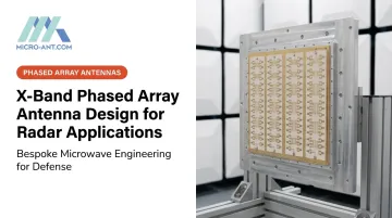
X-band phased array antenna design is the process of engineering a grid of radiating elements, each with individually controlled phase and often amplitude, operating between 8 and 12 GHz. When every element's signal timing is adjusted correctly, the combined wavefronts add constructively in a specific direction. That's the beam.
The goal is a compact, agile aperture that redirects its beam electronically fast enough to detect, track, and engage multiple targets before they close distance. No moving parts, no mechanical lag.
This differs from two common alternatives: mechanically scanned parabolic or reflector antennas, which produce a single beam and require motors to physically move the dish, limiting scan speed and introducing wear; and lower-frequency S-band or L-band arrays, which trade angular resolution for longer range and better weather penetration, useful for volume search but less precise for fire control.
AESA vs. PESA Architecture in X-Band Design
Two architectures dominate X-band radar design, and they're not interchangeable.
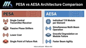
PESA (passive electronically scanned array) relies on one central transmitter/receiver feeding a network of passive phase shifters. It's simpler and cheaper, but that central RF chain, often a traveling-wave tube, becomes a single point of failure.
AESA (active electronically scanned array) gives every element its own transmit/receive module. Each module independently handles transmit power, receive amplification, and phase control. This distributed design enables:
- Simultaneous multi-beam operation (search and track at once)
- Graceful degradation when individual modules fail, rather than total loss
- Faster beam agility for multi-function radar tasks
A bespoke design approach doesn't default to AESA just because it's the more capable option on paper. It tailors element count, lattice spacing, and architecture, whether AESA, hybrid, or digital beamforming, to the actual mission profile rather than forcing a generic template onto every program.
Why X-Band Phased Arrays Are Used in Radar Applications
The 8-12 GHz range hits a sweet spot: enough angular resolution for precision targeting, sufficient range for tactical use, and a physical aperture size that fits on airborne, naval, and ground-based platforms with limited real estate.
That balance is driving real market growth. The active phased-array radar market is projected to climb from $5.05 billion in 2026 to $10.63 billion by 2034, a 9.76% CAGR according to Fortune Business Insights.
What Radar Missions Actually Demand
Modern radar applications need more than raw detection range. They require:
- Rapid multi-target tracking across a wide field of view
- Resistance to jamming and clutter in contested electromagnetic environments
- Reliable performance in adverse weather, even with the tradeoffs X-band accepts versus lower bands
- SWaP-C efficiency, since size, weight, power, and cost constraints shape nearly every platform decision
The Cost of Getting It Wrong
Mechanically scanned antennas struggle here. They track one target at a time, suffer wear from constantly moving parts, and can't react fast enough to threats like small UAVs that fly low, slow, and erratically to avoid detection.
AESA X-band design has become the industry default for multi-mission radar, and in many defense programs, it's close to mandatory. NAVAIR reports its APG-79 AESA delivers search-while-track performance and near-simultaneous air-to-air and air-to-ground scanning, claiming at least 10 times the capability of the legacy APG-73 it replaced.
That's a program-specific figure, not a universal ratio, but it illustrates the leap AESA architecture represents over mechanically scanned systems.
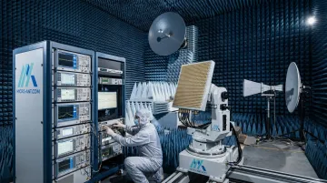
Specialized antenna manufacturers support this shift by pairing design expertise with in-house validation. Micro-Ant, for instance, offers AS9100:2016 and ISO 9001:2015-certified design and manufacturing alongside near-field and far-field testing chambers covering 750 MHz to 40 GHz. This lets defense and aerospace customers validate X-band radar antennas domestically without shipping hardware overseas.
How X-Band Phased Array Antenna Design Works
The design process moves from system requirements through architecture selection, RF front-end design, beamforming control, and validation testing. Mission requirements, scan volume, gain, and bandwidth combine with SWaP constraints and semiconductor choice (GaN or GaAs) to shape every downstream decision.
Phase shifters and attenuators in each transmit/receive channel adjust signal timing and amplitude so wavefronts combine constructively in the desired direction. Digital beamformer ICs and control software calculate real-time phase and amplitude coefficients for every element, steering and shaping the beam on the fly.
The result: a fixed physical array becomes a dynamically steerable aperture that scans a field of view within microseconds.
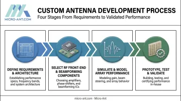
The process follows four sequential steps:
Define system requirements and array architecture. Element count, spacing, and lattice geometry trace back to required scan angle, sidelobe suppression, and grating lobe avoidance. Spacing typically stays near half-wavelength; at X-band, that's roughly 12.5 to 18.75 mm depending on the exact frequency. Push spacing beyond that threshold without accounting for scan angle, and grating lobes creep into the pattern, degrading detection accuracy.
Select RF front-end and beamforming components. This step determines GaN or GaAs T/R modules, beamformer ICs, and phase shifters based on power output, noise figure, and integration density. According to Qorvo's technical guidance on X-band beamforming components, GaN delivers higher power density and efficiency for transmit stages. GaAs remains competitive for very-low-noise receive functions, with some GaAs LNAs achieving noise figures below 1 dB. The right choice depends on which function in the signal chain you're optimizing.
Simulate and model array performance. Before committing to hardware, engineers run electromagnetic simulation and array factor modeling to predict gain, beamwidth, and sidelobe behavior. This step catches design flaws such as grating lobes, unexpected coupling, and gain shortfalls while changes still cost hours instead of tooling budgets.
Prototype, test, and validate. Near-field and far-field range testing, including the spherical and planar chambers Micro-Ant runs in-house, calibrates phase and amplitude error across every element. Environmental qualification (vibration and thermal testing) confirms the design holds up under field conditions before it ever reaches a platform.
Where X-Band Arrays Are Applied and Key Design Factors
Where the Design Is Applied
X-band phased arrays show up across:
- Airborne fire-control radar on fighter aircraft
- Naval AESA (Active Electronically Scanned Array) installations for horizon search and missile support
- Ground-based air defense radar
- Counter-UAV and surveillance systems tracking small, low-flying threats
Programs typically invest in new X-band array design during new platform development or through modernization and retrofit cycles. Common triggers include emerging small-drone threats, obsolescence of mechanically scanned legacy systems, and organizational mandates to cut SWaP-C (size, weight, power, and cost).
Key Factors That Affect X-Band Array Performance
A handful of variables determine whether an array performs to spec in the field:
| Factor | Impact |
|---|---|
| Substrate and GaN vs. GaAs choice | Drives power density and efficiency |
| Temperature, vibration, humidity | Can degrade phase stability if not engineered for |
| Beamformer IC integration and DC bias sequencing | GaN's negative gate bias requirement can damage components if sequenced incorrectly |
| Channel count | Dozens to thousands of transmit/receive (T/R) modules drive cost, thermal complexity, and calibration time |
| ITAR and MIL-STD requirements | Shape material choices, documentation, and testing protocols for defense programs |
Skip any one of these during design, and the array either underperforms in the field or fails qualification testing outright.
Common Misconceptions and When a Full Custom Array Isn't the Right Fit
Common Issues and Misconceptions
A few assumptions cause real problems in radar procurement:
- "Phased array" doesn't automatically mean AESA. Many fielded systems remain passive or hybrid, with different cost and performance tradeoffs that suit specific missions better.
- Beam steering isn't purely a software problem. RMS phase and amplitude error from component mismatches, temperature swings, and calibration drift degrades beam shape and detection accuracy, no matter how good the software is.
- Antenna gain and system sensitivity aren't the same thing. Sensitivity depends heavily on noise figure and RF front-end integration, not just how much gain the aperture produces on paper.
These misconceptions often steer teams toward a full custom AESA when a simpler architecture would serve the mission just as well.
When a Full Custom AESA Array May Not Be Appropriate
A full custom AESA isn't always the right call. Consider simpler mechanically scanned or PESA antennas when:
- The mission involves cost-sensitive, single-target tracking rather than multi-function operation
- SWaP-C budgets are so tight that thousands of T/R channels become impractical to power, cool, or integrate
- Teams default to X-band without checking whether S-band, Ku-band, or Ka-band better fits the mission's range, resolution, or weather-penetration needs
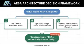
That last point trips up more programs than it should. Band selection deserves the same rigor as architecture selection.
Conclusion
X-band phased array antenna design moves from mission requirements through architecture selection, component choice, EM simulation, and validated testing to produce an electronically steerable radar aperture. Errors in any step, whether spacing, semiconductor choice, or phase error budget, show up directly in detection range, tracking accuracy, and mission safety.
Defaulting to a generic COTS antenna rarely serves a radar program well. Partnering with an experienced bespoke antenna design and manufacturing team, like Micro-Ant, gives program managers a path to mission-specific X-band radar antennas validated before they ever reach the field. Micro-Ant's engineers bring over 20 years of experience and domestic testing capability to that validation process.
Frequently Asked Questions
What is an X-band phased array antenna?
An X-band phased array antenna is an electronically steered antenna system operating in the 8-12 GHz range that uses phase-controlled elements to direct radar beams without any physical movement of the antenna itself.
What is the difference between AESA and PESA radar?
AESA gives each element its own transmit/receive module, enabling simultaneous multi-beam operation. PESA relies on one central transmitter/receiver feeding distributed phase shifters, which is simpler but less flexible.
Why is X-band preferred for many radar systems?
X-band balances angular resolution, detection range, and physical antenna size, making it practical for compact airborne, naval, and ground platforms that need high-precision target detection.
How many elements are typically used in an X-band phased array?
Element counts vary enormously, from dozens in small tactical systems to over 20,000 in large defense radar arrays, depending on required gain, scan volume, and mission complexity.
What causes phase and amplitude errors in phased array antennas?
Component mismatches, temperature variation, mutual coupling between elements, and calibration drift all introduce RMS phase and amplitude errors that degrade beam shape and detection accuracy.
How long does it take to design and test a custom X-band phased array antenna?
Timelines vary by complexity, but most programs move through simulation, prototyping, and RF/environmental validation before deployment. Micro-Ant's in-house design-build-test facility and near-field test chambers help compress this timeline without sacrificing accuracy.