Circular polarization (CP) isn't a design footnote. It's the property that determines whether a link closes reliably when the receiving antenna's orientation is unpredictable, which describes most satcom, GNSS, and mobile platforms in the field. A CP antenna with an axial ratio (AR) of just 2.44 dB already shows measurable cross-polarization discrimination degradation, down to roughly 17.1 dB from a theoretical ideal, according to MEGIQ's technical breakdown of axial ratio. That gap between lab-ideal and field-real is what this article unpacks.
We'll cover what CP actually represents, the axial ratio range that separates good designs from marginal ones, the technical properties engineers must trade off, how AR gets measured and validated, and what happens when it drifts out of spec.
Key Takeaways
- Circular polarization eliminates orientation-dependent signal loss by rotating, not fixing, the E-field plane
- Axial ratio near 0 dB signals near-perfect CP; under 3 dB is the industry benchmark for acceptable performance
- AR stays low only within a narrow frequency band and degrades with feed imbalance, tolerances, and mounting conditions
- RHCP and LHCP antennas cannot communicate with each other, no matter how clean each one's AR looks
- Poor AR reintroduces the very polarization losses CP was designed to eliminate
What Circular Polarization Represents in Antenna Systems
Circular polarization happens when an antenna radiates two orthogonal linearly polarized field components of equal magnitude, offset by a 90-degree phase difference. The result: the resultant E-field vector rotates through a full 360 degrees every wave cycle instead of staying fixed to one plane. Reverse the phase relationship, and the rotation sense flips too.
CP is an output characteristic of the antenna's physical geometry: patch symmetry, helix winding direction, crossed-dipole feed timing. Engineers set it intentionally at the architecture stage, using diagonal-symmetric patch corners, helical elements, or precisely phased feed networks. Once built, it gets validated as an operating variable: axial ratio.
Factors That Influence CP in Real-World Operation
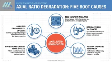
A simulation model can show a perfect 0 dB AR. Real hardware never quite gets there, and several factors explain the gap:
- Feed network imbalance: Phase and amplitude mismatch between the two orthogonal modes widens axial ratio. A 2019 URSI AP-RASC study of a dual-fed S-band patch found AR most sensitive to amplitude imbalance between feeds.
- Manufacturing tolerances: Dielectric thickness variation in high-permittivity stacked patches shifts the frequency where AR is minimized and degrades boresight performance.
- Narrow operating bandwidth: AR stays low only across a band centered tightly on the design frequency, unlike impedance match bandwidth, which is usually much wider.
- Mounting and ground plane effects: Asymmetric ground plane reduction and coupling to nearby structures on an airframe or vehicle body distort polarization purity. GPS L1 studies document this effect and demonstrate feed correction techniques for specific installed environments.
- Aging and environmental exposure: Thermal cycling and material degradation over years of field deployment can gradually shift AR, though the rate depends heavily on materials and enclosure design.
Range of Axial Ratio in CP Antennas
CP quality isn't governed by a single fixed number. It's bounded by design targets and the antenna's usable frequency band.
Nominal Operating Range
The industry-accepted benchmark for "good CP" is an AR under 3 dB, measured at boresight under lab or anechoic chamber conditions with proper feed matching.
High-performance designs, including many GNSS and satcom feeds, push well below that line, often approaching 1 dB near center frequency. No single ICD or operator specification mandates that number universally, but it's the de facto target for demanding applications.
Allowable Tolerance and Boundary Limits
Beyond roughly 3 dB, cross-polarization discrimination degrades noticeably, and the antenna starts behaving more like a poorly matched linear system. Two design categories handle this differently: narrowband CP antennas hold low AR across a few hundred MHz and are comparatively easy to tune, while wideband or multi-band CP antennas must maintain acceptable AR across gigahertz-wide spans, a much harder problem involving trade-offs in feed geometry and element symmetry.
Safe Operating Margin
Engineers don't design to the 3 dB line. They design margin below it across the full temperature range, frequency band, and beam angle, not just at a single test point.
Operating close to the boundary leaves no room for drift. A few degrees of thermal expansion or a year of moisture ingress can be enough to push a marginal design into unacceptable cross-polarization loss.
Key Technical Properties of CP Antennas
CP performance comes down to three interacting properties: axial ratio stability, polarization sense, and pattern behavior across the beam.
Axial Ratio Stability and Variability
AR doesn't just vary with frequency. It varies with observation angle off boresight, and this AR beamwidth is highly design-dependent. Published examples span a wide range:
| Application | Frequency | 3 dB AR beamwidth |
|---|---|---|
| L-band CP antenna | 1.16–1.46 GHz | Greater than 120° |
| CP microstrip antenna | 1.566–1.582 GHz | Approximately 170° |
| Wide-angle GNSS antenna | — | Greater than 200° |
There's no universal "typical" figure here; it's architecture- and installation-specific.
Unit-to-unit repeatability matters just as much as the design number. If manufacturing tolerances aren't tightly held, AR performance can shift batch to batch.
This is one area where Micro-Ant's ISO 9001:2015 and AS9100:2016-certified manufacturing processes support consistent AR across production runs. Aerospace-grade quality systems build in the dimensional controls that CP geometry depends on.
Polarization Sense: RHCP vs. LHCP
Handedness matters as much as AR. An RHCP antenna and an LHCP antenna will not communicate efficiently, even if both show excellent individual axial ratio numbers. Sense has to match at both ends of the link.
GNSS signals make this concrete. GPS's IS-GPS-200N interface specification requires that transmitted signals be right-hand circularly polarized, and Galileo's OS SIS ICD states the same for its own constellation. Every GNSS receive antenna, therefore, has to be designed and validated as RHCP. Get the sense wrong, and no amount of gain fixes it.
Coupling with Gain, Bandwidth, and Trade-offs
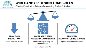
Achieving very low AR across a wide bandwidth rarely comes free. Designers typically trade off:
- Peak gain often drops, since achieving CP purity across more frequency means accepting a flatter, less peaked pattern
- Feed networks grow more complex, as wideband CP typically demands sophisticated phasing circuitry and a larger physical footprint
- Manufacturing margin shrinks, because tighter AR specs leave less room for dimensional drift
Ultra-wideband Ka-class systems illustrate this well. A design that needs to roam across multiple satellite operators and frequency plans has to hold acceptable AR across a much larger swath of spectrum than a single-operator terminal. That balancing act is exactly what shaped Micro-Ant's award-winning Ultra-Wide Band (3.5 GHz) Ka Antenna System.
How Circular Polarization Is Specified, Measured, and Validated
AR isn't just a datasheet line. It's a design specification and an operational check performed during acceptance testing.
Specification and Documentation
CP antennas are documented with a rated AR in dB over a stated frequency band and beam angle, alongside declared polarization sense. Two numbers matter here:
| Value Type | What It Means |
|---|---|
| Rated values | Worst-case guaranteed performance across the full specified band and environment |
| Typical values | Measured results shown in test reports, often better than the rated floor |
Confusing the two is a common procurement mistake, since a "typical" AR number from a test report isn't the same guarantee as a rated spec.
Measurement and Verification Methods
The most common technique is the spinning-linear method, standardized under IEEE 149. A linearly polarized probe rotates about the propagation axis while received amplitude is recorded; the ratio of maximum to minimum field amplitude gives the AR directly. A dual-linear probe method achieves the same result without mechanical rotation, using calibrated orthogonal channels instead.
Measurement accuracy depends heavily on chamber quality and calibration. Lab-measured AR under ideal anechoic conditions can differ meaningfully from field performance once mounting structure and multipath enter the picture.
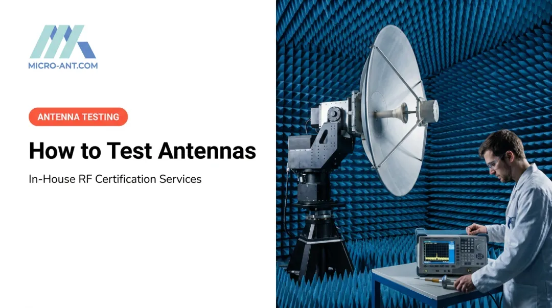
This is why in-house, quick-turnaround testing matters. Micro-Ant's spherical and planar near-field chambers, covering 750 MHz to 40 GHz, let engineering teams validate CP performance before a design ever leaves the facility. This cuts the travel time that third-party test ranges typically add.

Implications of Poor Axial Ratio and Common Misinterpretations
As AR widens beyond nominal design values, the radiated wave becomes more elliptical, and polarization-dependent signal loss creeps back in, the exact problem CP was supposed to eliminate.
The mechanism is measurable. Cross-polarization discrimination (XPD) falls as AR rises, following a direct mathematical relationship. Satellite operators build this into acceptance testing: Eutelsat's ESOG 120 standard requires type-approval XPD greater than 27 dB in C-band and 30 dB in Ku/K/Ka bands for circularly polarized systems above 50 watts.
Lower discrimination means more energy lands in the wrong polarization. This degrades link margin, particularly for mobile or roaming satcom terminals and GNSS receivers operating in urban or foliage-heavy environments.
Common Misinterpretations to Avoid
Two misinterpretations show up repeatedly in procurement and integration:
- Treating a single "best AR" number as valid everywhere — AR typically stays low only near center frequency, not across the whole operating band
- Ignoring sense mismatch: pairing an RHCP antenna with an LHCP counterpart causes severe signal loss no matter how clean each antenna's individual AR looks
Conclusion
Axial ratio and polarization sense are governance parameters, not specifications to skim past. They decide whether a CP antenna performs as designed once it's mounted on a real airframe, mast, or hull.
Understanding CP's real-world range, not just its lab-ideal number, separates a link that closes reliably from one that fades unpredictably.
Engineering judgment, rigorous testing, and manufacturing precision matter just as much as the AR number printed on a datasheet. That's the standard defense, aviation, maritime, and satcom programs should hold every antenna supplier to, Micro-Ant included, with every custom CP antenna verified through in-house near-field range testing before it ships.
Frequently Asked Questions
What is a circular polarized antenna?
A CP antenna radiates a wave whose electric field rotates, either right-hand (RHCP) or left-hand (LHCP), rather than staying fixed on one plane. This allows consistent reception regardless of the receiving antenna's orientation.
What is a good axial ratio for a CP antenna?
An axial ratio under 3 dB provides acceptable CP performance for most designs. High-performance GNSS and satcom antennas often target closer to 1 dB near their center frequency.
Can an RHCP antenna communicate with an LHCP antenna?
No. Mismatched polarization sense causes severe signal loss, so both ends of a link need matching RHCP or LHCP antennas to communicate efficiently.
Why do GPS and GNSS antennas use RHCP?
GPS and Galileo satellites broadcast RHCP signals per their published interface control documents. Receiving antennas must therefore be RHCP to capture the signal correctly.
How is axial ratio measured on a CP antenna?
Engineers commonly use the spinning-linear method under IEEE 149, rotating a linear probe to compare maximum and minimum field amplitude. Alternatively, a dual-linear probe method uses calibrated orthogonal channels in an anechoic or near-field chamber.
Does circular polarization reduce signal strength compared to linear polarization?
CP itself doesn't reduce theoretical signal strength. It trades some peak gain for consistent, orientation-independent reception, which is a worthwhile exchange for most mobile and satellite applications.