Introduction
Program teams building defense, aviation, maritime, or land-based communications systems face a decision that shapes everything downstream: UHF or VHF antenna architecture. Get it wrong, and the consequences aren't minor.
Many engineers struggle with this trade-off because range, size, and data throughput pull in opposite directions. A VHF antenna sized for long-range voice communications won't fit inside a low-profile aircraft fairing.
A UHF array optimized for satcom data rates, meanwhile, may lack the penetration a ground unit needs in dense terrain.
Choose wrong and you're looking at costly redesigns, unreliable field connectivity, or a failed environmental test just before a program milestone.
This guide breaks down frequency fundamentals, core UHF/VHF differences, design principles, and ruggedization requirements. It also covers what to look for in a design partner capable of delivering field-ready hardware the first time.
Key Takeaways
- VHF favors long-range, obstacle-tolerant voice links; UHF enables faster data and compact hardware
- Antenna size scales directly with wavelength, so VHF hardware is inherently larger for equivalent gain
- Reliable designs balance frequency, gain, polarization, impedance, and bandwidth against manufacturing reality
- Mission-critical builds require rugged construction, wideband roaming capability, and full near-field/far-field validation
- An experienced, certified manufacturing partner shortens qualification cycles and reduces field failures
What Are UHF and VHF Frequencies?
The International Telecommunication Union defines VHF as 30-300 MHz, corresponding to wavelengths of roughly 10 meters down to 1 meter. UHF spans 300 MHz to 3 GHz, with wavelengths from about 1 meter down to 10 centimeters (ITU-R V.431-8).
That wavelength gap drives almost every downstream design decision. Shorter UHF wavelengths mean smaller radiating elements, tighter arrays, and higher achievable data rates. Longer VHF wavelengths mean bigger hardware, but signals that travel farther and diffract around obstacles more readily.
Common use-case anchors:
- VHF: aviation and marine voice radio, FM broadcast, land mobile radio
- UHF: satcom terminals, GNSS, RFID, radar, tactical data links, telemetry
Neither band is "better." They're tools suited to different link budgets, and the right choice depends on what the mission actually requires.
UHF vs VHF Antennas: Key Differences That Impact Design
Propagation behavior is where the two bands diverge most in practice. VHF signals travel via ground-wave and line-of-sight paths, and the FAA notes that greater altitude directly extends VHF communication range for aircraft (FAA Chapter 4). UHF trades some of that range for better performance in cluttered environments, though the advantage isn't universal.
Building penetration is a good example. ITU measurement data across 460-1,860 MHz found a mean excess path loss around 30 dB, with roughly 8 dB standard deviation, and losses that climbed 8-10 dB deeper into a structure (ITU-R P.2346-3). Frequency alone doesn't determine penetration: structure, depth, and geometry matter just as much.
A Worked Size Comparison
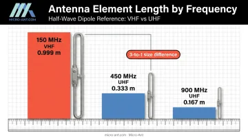
Using λ = c/f with the exact speed of light, the ideal half-wave dipole length looks like this:
| Frequency | Band | Wavelength | Ideal Half-Wave Length |
|---|---|---|---|
| 150 MHz | VHF | 1.999 m | 0.999 m |
| 450 MHz | UHF | 0.666 m | 0.333 m |
| 900 MHz | UHF | 0.333 m | 0.167 m |
That's a 3-to-1 size difference between a VHF and UHF element at these frequencies, before accounting for conductor diameter, radomes, or matching hardware. This is why UHF hardware fits inside a UAV fairing while a comparable VHF whip cannot.
Frequency also shapes gain and aperture in a related way. NASA's smallsat communications guidance notes that higher frequencies deliver more gain for a given physical aperture, though propagation losses rise alongside frequency (NASA SmallSat State of the Art). That's why UHF phased arrays can pack meaningful gain into a compact footprint for satellite tracking, while VHF arrays need more real estate for the same directivity.
The same relationship extends to data throughput. UHF's nominal band spans roughly ten times the frequency range of VHF, which supports wider channel allocations. Actual data rate still depends on Shannon capacity: channel bandwidth and signal-to-noise ratio, not the band label alone.
| Attribute | VHF | UHF |
|---|---|---|
| Frequency Range | 30-300 MHz | 300 MHz-3 GHz |
| Wavelength | 10-1 m | 1-0.1 m |
| Typical Antenna Size | Larger elements, longer booms | Compact elements, dense arrays |
| Effective Range | Longer over open terrain/sea | Shorter, but structure-dependent |
| Common Applications | Marine/aviation voice, broadcast | Satcom, radar, GNSS, tactical data links |
Multipath behavior adds a final variable, one that plays out differently depending on the environment. Maritime links contend with sea-surface reflection and scattering that intensify with wide-beam antennas and sea state (ITU-R P.680-4). Aviation links add Doppler effects from aircraft speed on top of surface reflections. Both scenarios demand pattern and polarization choices tailored to the actual platform, not a generic band assumption.
Core Engineering Principles in UHF/VHF Antenna Design
Every design starts with λ = c/f. Engineers use that relationship to derive half-wave and quarter-wave element lengths as a starting point, then adjust for conductor diameter, feed structure, and nearby materials. That baseline number is arithmetic. The real engineering happens in matching, pattern shaping, polarization, and bandwidth.
Impedance Matching
Most RF systems target 50 ohms as the reference impedance (Rohde & Schwarz). VSWR quantifies how much signal reflects back toward the source instead of radiating. A 1:1 ratio is ideal; anything higher means wasted power and, at extremes, risk to transmitting hardware.
Common matching techniques include:
- T-match: adjusts feed point impedance without altering element length
- Gamma match: asymmetric variant suited to single-feed Yagi designs
- Stub tuning: adds a controlled reactance via a transmission-line stub
Gain, Directivity, and Radiation Pattern
Omnidirectional designs (ground plane, loop, J-pole) spread coverage evenly across azimuth, which suits mobile and local-area links. Directional designs (Yagi, helical, patch) concentrate energy toward a target.
Gain scales with boom length and element count in Yagi designs. NIST's own 400 MHz design series measured 7.1 dB at 0.4λ boom length, climbing to 14.2 dB at 4.2λ (NIST Technical Note 688). Longer booms buy more gain, but at the cost of size, weight, and wind loading, a real constraint for shipboard and aircraft-mounted hardware.
Polarization
Linear polarization works fine for many terrestrial links. Satcom is different. As a signal passes through the ionosphere, its polarization plane can rotate, an effect that increases at lower frequencies. Circular polarization sidesteps this, which is why it's specified so often for satellite links, though it doesn't eliminate sea-reflection multipath or blockage on its own.
Bandwidth Engineering for Multi-Operator Roaming
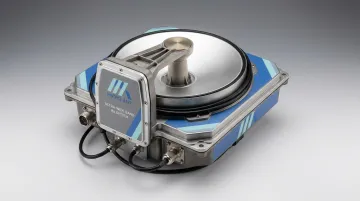
Wideband designs that roam across multiple satellite operators demand serious trade-offs in element geometry and matching networks. Micro-Ant's Ultra-Wide Band Ka Antenna System illustrates the challenge: it covers 17.7-21.2 GHz on receive and 27.5-31 GHz on transmit, a 3.5 GHz span on each sub-band, while holding axial ratio below 1 dB across the entire bandwidth. Hitting that spec required new manufacturing tolerances on critical components, not just a clever feed design.
Material and substrate choices matter too. Components need resonant stability as temperature swings across a mission profile, since thermal drift in a substrate can shift the operating frequency out of spec at exactly the wrong moment.
Designing for Rugged, Mission-Critical Applications
Antennas destined for a ship deck, an aircraft skin, or a forward operating base face conditions catalog products were never built for. Environmental durability engineering has to be tailored to the actual platform, not assumed from a generic spec sheet.
Environmental factors to plan for:
- Temperature extremes across storage and operational ranges
- Vibration and shock during transport and operation
- Saltwater corrosion in maritime and coastal deployments
- Solar loading and UV exposure for topside installations
MIL-STD-810H governs environmental engineering and lab testing, with Method 514.8 covering vibration and Method 516.8 covering shock. MIL-STD-461G governs EMI emissions and susceptibility separately. Both matter, but a vendor's blanket "MIL-STD compliant" claim isn't specific enough: ask which methods, which severities, which axes were tested.
Passing those tests only confirms the design survives the environment on paper. Manufacturing tolerance sensitivity is easy to overlook by comparison.
Small deviations in element length or spacing during fabrication shift resonant frequency, and that shift shows up as degraded field performance months later, not on the bench. Tighter tolerance control becomes more critical as bandwidth widens.
Multi-band and cross-operator roaming adds another layer: hardware needs to maintain connectivity across multiple satellite operators or frequency allocations without a swap-out. Validation has to prove it works, not just theorize it.
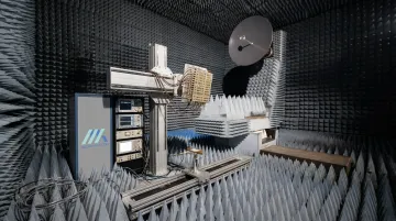
That validation happens in anechoic chambers across the full operating range. Micro-Ant runs spherical and planar near-field testing chambers spanning 750 MHz to 40 GHz, covering everything from VHF-adjacent UHF designs through Ka-band systems in-house.
Quality certifications round out the picture: AS9100:2016 for aerospace and defense quality management, and ISO 9001:2015 as the cross-sector quality management baseline.
Neither certification proves RF performance on its own, but both signal traceable, controlled manufacturing that defense and aerospace supply chains require before they'll qualify a vendor.
Weatherproofing, connector sealing, and radome design add another layer of protection, shielding the RF path from the same salt, moisture, and vibration the environmental tests simulate.
Choosing the Right UHF/VHF Antenna Design Partner
Off-the-shelf catalog antennas rarely fit mission-critical platform constraints. Look instead for a manufacturer with a track record of bespoke design across defense, aviation, maritime, and land programs.
What to evaluate:
- Custom design history: Micro-Ant has developed more than 1,000 custom antenna products over 20+ years, spanning parabolic, flat panel, phased array, and shipboard designs
- In-house testing: US-based chambers reduce travel time and shorten qualification cycles compared to shipping hardware overseas for third-party testing
- Certifications: AS9100:2016 and ISO 9001:2015 signal manufacturing discipline defense programs expect
- Customer references: experience with global satellite operators (Intelsat, Inmarsat, Iridium, Eutelsat, Thuraya) and defense programs like ARSTRAT demonstrates real-world qualification history
A partner that designs, manufactures, and tests under one roof avoids the coordination gaps that slow down custom antenna programs. Micro-Ant handles all three functions at its Jacksonville, Florida facility, rather than splitting them across separate vendors.
Frequently Asked Questions
What makes a good UHF antenna?
A good UHF antenna matches gain and directivity to the application while holding a proper impedance match with low VSWR. It also uses the right polarization and survives the deployment environment without degrading over time.
What is the main difference between UHF and VHF antennas?
VHF covers 30-300 MHz with 10-1 meter wavelengths, while UHF covers 300 MHz-3 GHz with 1-0.1 meter wavelengths. That size gap means VHF favors longer range at lower data rates, while UHF enables compact hardware and higher throughput.
How do you calculate the size of a UHF or VHF antenna?
Start with λ = c/f to get the free-space wavelength, then derive half-wave or quarter-wave element lengths. Actual dimensions also depend on element type, conductor diameter, and nearby materials or structures.
Can one antenna cover both UHF and VHF bands?
Dual-band and wideband designs exist, but they typically trade off gain or efficiency compared to a single-band optimized antenna. The wider the bandwidth target, the harder it gets to hold performance across the entire range.
Why does impedance matching matter in antenna design?
A proper match minimizes signal reflection and maximizes power transfer to the antenna. A mismatch, measured as high VSWR, cuts effective range and can damage transmitting equipment over time.
How long does custom UHF/VHF antenna design typically take?
Timelines vary with complexity and testing scope, ranging from a few weeks for a simple design to several months for a phased-array or EW system. Micro-Ant handles design, fabrication, and testing in-house at its Jacksonville facility, which shortens the qualification cycle compared to coordinating across multiple vendors.