Space antennas can't be repaired. They can't be swapped out when a bolt loosens or a coating degrades. Engineers get one shot to get it right, and the margin for error shrinks with every mile past the atmosphere.
That's the pain point program managers live with daily: choosing an antenna architecture and a manufacturing partner that can survive launch, vacuum, and radiation while still hitting exact RF performance specs. Get it wrong, and you've jeopardized an entire mission.
This guide walks through what makes space antenna engineering unique, the major antenna types flying today, the design criteria that matter most, and what separates a capable manufacturing partner from a risky one.
Key Takeaways
- Space antennas must endure storage, launch, and years in orbit, not just meet RF specs.
- Mission type shapes design: GNSS, SATCOM, deep space, and TT&C need different antennas.
- Materials, thermal stability, and qualification testing matter as much as RF design.
- A certified manufacturing partner speeds the path from concept to flight-ready hardware.
What Makes Antenna Design for Space So Different
A terrestrial antenna that fails gets serviced. A space antenna that fails becomes permanent mission damage. That single fact reshapes every design decision, from material selection to fastener torque, because there's no second chance once the payload separates from the launch vehicle.
Vacuum, Outgassing, and Venting
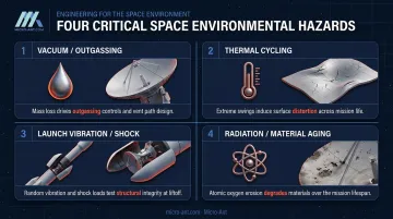
Materials that seem stable on the ground can behave badly in a vacuum. Certain polymers and adhesives release volatile compounds, a process called outgassing, that can condense on sensitive optics or nearby subsystems.
Space agencies screen materials tightly for this reason. ESA's general screening criteria call for recovered mass loss below 1.0% and collected volatile condensable material below 0.1% before a material earns approval for flight use.
Enclosed cavities present a separate problem. As a rocket ascends, cabin and fairing pressure drops fast, and any sealed pocket inside an antenna assembly needs a path to vent that pressure or risk structural damage.
NASA Ames guidance requires vented volume-to-area ratios below 2,000 cubic inches per square inch, with vent area sized at least twice the rate calculated for the launch profile's depressurization. Skipping that calculation risks a cracked radome before the antenna ever reaches orbit.
Extreme Thermal Cycling
Satellites swing between blistering sunlight and freezing shadow every orbit, sometimes multiple times per day. That constant temperature swing makes structures expand and contract, an effect engineers call "breathing."
For reflector antennas, this breathing isn't cosmetic. NASA research identifies thermally induced surface distortion as a direct cause of pointing errors, reduced peak gain, elevated sidelobes, and cross-polarization degradation. A 2024 deployable-reflector study measured surface deviation of 0.878 mm at -60°C, with shifts of 0.216 mm and 0.411 mm for 40°C and 80°C temperature changes respectively.
Small numbers, but at higher frequencies where wavelengths shrink, a fraction of a millimeter of surface error can meaningfully shift where the beam points.
Launch Vibration and Shock
Liftoff subjects hardware to violent random vibration and shock loads, and every launch vehicle imposes a different environment. A payload riding inside a smallsat dispenser sees a different load path than one directly bolted to a spacecraft bus.
Standards like ECSS-E-ST-10-03C set qualification vibration testing at 6 dB above acceptance levels for 2.5 minutes per axis, while military standard SMC-S-016 specifies similar margins for defense programs. But these are baseline rules, not a substitute for the actual interface-control document.
NASA's CubeSat guidance is explicit on this point: the mission-specific ICD between spacecraft and dispenser supersedes generic requirements. Design teams that skip this step and build to a generic spec risk a mismatch discovered only during integration, when fixes are expensive and schedules are tight.
Radiation and Material Aging
Low Earth orbit spacecraft face a steady bombardment of atomic oxygen, UV exposure, and ionizing radiation, all of which degrade materials over time. NASA's MISSE flight experiments measured atomic oxygen fluence as high as 8.51 × 10²¹ atoms per square centimeter over roughly four years of exposure on the MISSE 1/2 missions.
That erosion doesn't hit every material the same way. Kapton, a common spacecraft polymer, shows measurable erosion under this exposure, which is why radomes and protective coatings often get added over exposed antenna elements.
The catch: any coating added for protection also changes the RF path, so its dielectric properties have to be factored back into the electromagnetic design, not bolted on as an afterthought.
Common Types of Space Antennas and Their Applications
No single antenna design serves every space mission. Architecture depends on frequency band, gain requirements, and whether the spacecraft needs a fixed beam or one that moves electronically.
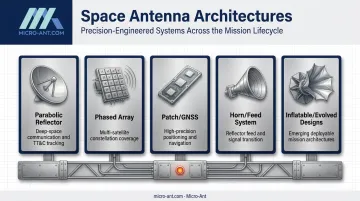
Parabolic Reflector and Dish Antennas
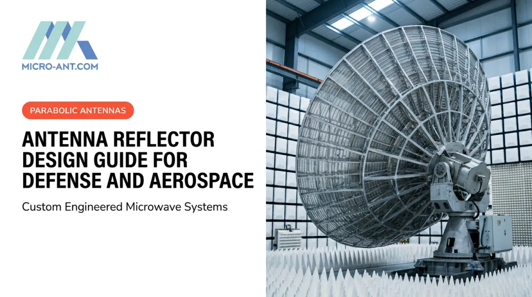
Reflector antennas remain the workhorse for deep-space communication and tracking, telemetry, and command (TT&C) links. Their concave shape concentrates energy into a narrow, high-gain beam, which is essential when a signal has to travel hundreds of millions of miles.
NASA's Deep Space Network illustrates the scale involved. A 34-meter beam-waveguide antenna delivers roughly 68.2 to 68.3 dBi of gain at X-band, while the network's larger 70-meter dishes reach 73.23 dBi ± 0.2 dB on X-band transmit. Gain figures like these only mean something when paired with frequency, elevation, and feed configuration, since all three shift the number substantially.
Phased Array Antennas
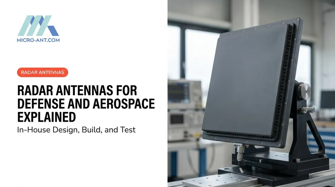
Phased arrays trade a single large aperture for many small elements that steer a beam electronically, with no moving parts. That matters enormously for constellations that need to track multiple satellites simultaneously or hand off between operators without physically repointing.
The scale of adoption is hard to overstate. Each Starlink satellite carries five Ku-band phased-array antennas, and the constellation had grown past 9,000 active satellites by 2025.
At that volume, procurement involves far more than raw RF performance. Buyers also have to weigh:
- Calibration consistency across thousands of array elements
- Thermal dissipation management at scale
- RF-chain redundancy, so a single failed element doesn't take down the beam
Patch and GNSS Antennas
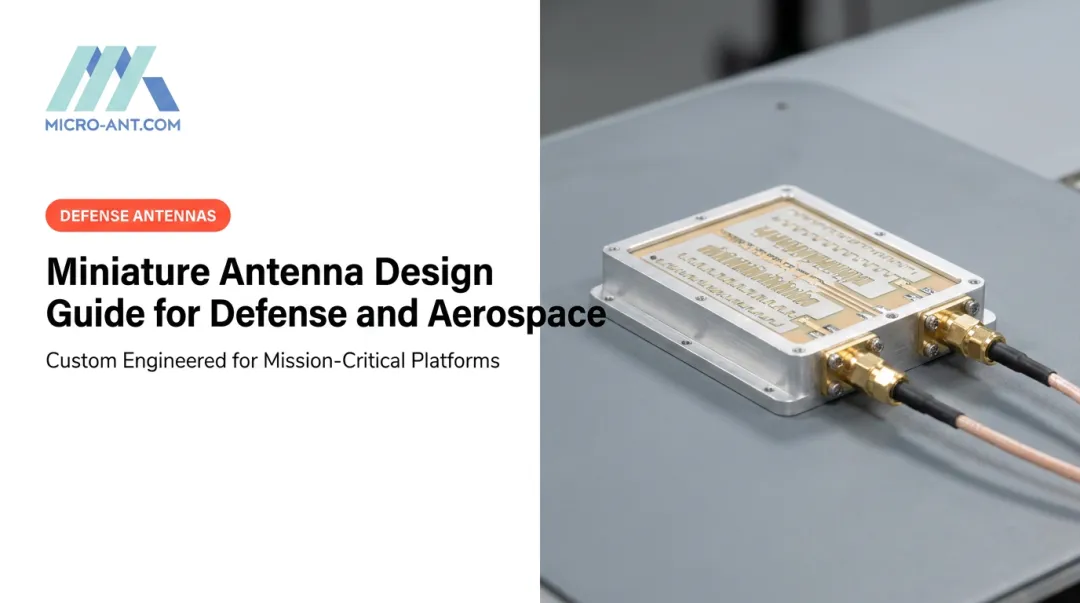
Patch antennas offer a compact, low-profile footprint that fits naturally onto small spacecraft where mass and volume are tightly constrained. They're the standard choice for GNSS reception and precision positioning payloads.
Not every "space-qualified patch" claim means the same thing, though. Vendor offerings typically fall into three tiers:
- GPS-only patches for basic single-constellation reception
- GPS/Galileo dual-constellation active patches
- TRL 9 all-constellation antennas covering GPS, Galileo, GLONASS, and BeiDou Treating those tiers as interchangeable during procurement is a common and costly mistake.
Horn Antennas and Feed Systems
Horn antennas rarely stand alone in space missions. Instead, they serve as feed elements that illuminate a parabolic reflector, delivering broadband performance with minimal insertion loss. NASA's SMAP mission, for example, uses a dual-polarized, dual-frequency corrugated feed horn paired with a 6-meter deployable mesh reflector covering both radar and radiometry bands from a single aperture.
Emerging Designs: Inflatable and Evolved Antennas
Two NASA programs point toward where the field is heading. The Large Balloon Reflector uses an inflatable spherical structure to achieve a wide aperture at a fraction of the mass of a conventional deployable dish, solving a mass problem that traditional geometries can't.
The ST5 mission took an even stranger path. Engineers ran a genetic algorithm for days to evolve an X-band antenna shape no human would have sketched by hand. NASA built and flew it, and it became the first computer-evolved hardware deployed in space, reportedly outperforming the original contractor design in ground testing.
Key Design Criteria for Space Antenna Engineering
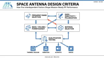
Space antenna design isn't a sequential process where you nail the electromagnetics first and worry about mechanics later. Every constraint applies at once, and tradeoffs in one area ripple into the others.
Frequency band selection comes first, and mission type usually dictates it:
- L-band for GNSS and lower-rate navigation links
- X-band for deep-space TT&C, where JPL's Deep Space Network operates uplinks near 7.145–7.190 GHz and downlinks near 8.400–8.450 GHz
- Ku and Ka-band for high-throughput SATCOM, where wider bandwidth supports more data per beam
Gain, directivity, and polarization shape the physical form of the antenna. A high-gain deep-space link needs a large reflector. A multi-beam SATCOM terminal roaming across operators needs an array that can reshape its pattern electronically. Circular polarization dominates most satellite links to reduce sensitivity to spacecraft orientation.
Mass, volume, and power budgets are unforgiving on a launch vehicle. Every gram of antenna structure competes with fuel, payload, and other subsystems, which is why lighter architectures like phased arrays and segmented composite reflectors, such as Micro-Ant's Veritas tri-band reflector system, keep gaining ground over heavier fixed dishes.
Material selection is a genuine balancing act. A dielectric substrate needs the right permittivity for RF performance, but it also has to survive thermal cycling, resist outgassing, and hold mechanical tolerance under vibration. Optimizing for one property alone almost guarantees a problem somewhere else in the design.
Finally, qualification testing closes the loop. Hardware only earns flight status after it clears the actual mission environment, not a generic checklist:
- Thermal-vacuum cycling validates performance across orbital temperature extremes
- Random vibration testing confirms structural integrity under launch loads
- Acoustic testing checks for resonance in lightweight panel and reflector materials
- Shock testing verifies survival of deployment and stage-separation events
Engineering Across the Full Mission Lifecycle
Antenna design doesn't start at launch. It starts the day materials arrive at the manufacturing facility and continues through years of operation. Skipping any phase of that lifecycle invites failure later.
Three factors carry the most weight throughout this lifecycle:
- Storage conditions: Limited-shelf-life materials like certain adhesives and composite prepregs degrade based on temperature, humidity, and light exposure long before a satellite reaches the pad, so ECSS-Q-ST-70-22C mandates controlled storage and full traceability.
- Qualification testing: A vibration test built around generic assumptions won't catch issues specific to a dispenser-mounted smallsat versus a directly attached payload. The interface-control document for the actual launch vehicle and orbit should drive the test plan.
- Documentation: Batch records, cure logs, storage history, and contamination-control data must travel with the hardware through integration. When a component fails review months after fabrication, that paper trail is often the only way to trace the root cause before it becomes a launch delay.
Choosing the Right Antenna Design and Manufacturing Partner
Off-the-shelf antennas rarely fit a specific spacecraft's frequency plan, gain budget, and environmental profile. In this industry, bespoke engineering is the baseline requirement.
Micro-Ant has spent over 20 years designing more than a thousand bespoke antenna products for defense, aerospace, and SATCOM programs. Its portfolio includes the award-winning Ultra-Wide Band (3.5 GHz) Ka Antenna System and a line of high-precision GNSS designs built for multi-constellation support.
That kind of track record matters when a program can't afford a redesign cycle mid-schedule.
A few things worth checking when evaluating any space antenna partner:
- In-house testing infrastructure — Near-field and spherical chambers covering 750 MHz to 40 GHz keep qualification data in-house, not at a third-party lab
- Aerospace-grade certifications — AS9100:2016 and ISO 9001:2015 both require documented risk management and process control, reducing the odds of unit-to-unit inconsistency
- Operator heritage — Micro-Ant holds certifications and flight heritage with SES, Eutelsat, Intelsat, Inmarsat, and Iridium, spanning GEO, MEO, and LEO programs across commercial and government domains
A manufacturer with that combination of design history, in-house test capability, and operator-recognized certifications typically shortens the qualification timeline considerably, simply because fewer surprises turn up during environmental testing.
Frequently Asked Questions
What frequency bands are commonly used for space antennas?
L-band handles most GNSS and navigation links, while X-band serves deep-space and TT&C communication. Ku and Ka-band add the wider bandwidth needed for high-throughput SATCOM applications.
How do space antennas differ from terrestrial antennas?
Space antennas must withstand vacuum and radiation exposure, plus the extreme mechanical loads of launch, all without any chance of repair. Terrestrial antennas, by contrast, can simply be serviced or replaced when something fails.
What is a phased array antenna used for in space?
Phased arrays enable electronic beam steering with no moving parts, making them ideal for satellite constellations that need to track multiple targets or switch between operators seamlessly.
How long does it take to design and qualify a space antenna?
Timelines vary widely based on complexity. Most programs move through iterative electromagnetic design and prototype testing, then a dedicated environmental qualification campaign tailored to the specific mission.
What certifications should a space antenna manufacturer have?
AS9100 and ISO 9001 are the clearest indicators of aerospace-grade quality management and traceability. Both certifications also signal the process control rigor needed for mission-critical hardware.
Can antennas be customized for specific satellite missions?
Yes. Bespoke design is standard practice in this industry. Frequency plans, gain requirements, and environmental profiles differ enough between missions that off-the-shelf hardware rarely fits.