The conical horn antenna has earned its place in that environment. Its flared, cone-shaped structure and circular symmetry make it a go-to choice for radar, SATCOM, and GNSS applications where reliability isn't negotiable.
This guide breaks down how conical horns work, why defense and aerospace programs keep specifying them, and what separates a capable manufacturing partner from one that just makes parts.
Key Takeaways
- Conical horns transition energy from circular waveguide to free space with minimal reflection loss.
- Their rotational symmetry naturally supports circularly polarized feeds for SATCOM and GNSS.
- Gain typically ranges from 10 to 25 dBi depending on aperture size and application.
- No moving or resonant parts means fewer failure points in high-vibration environments.
- Manufacturing partner selection should hinge on certifications, testing infrastructure, and program history.
What Is a Conical Horn Antenna?
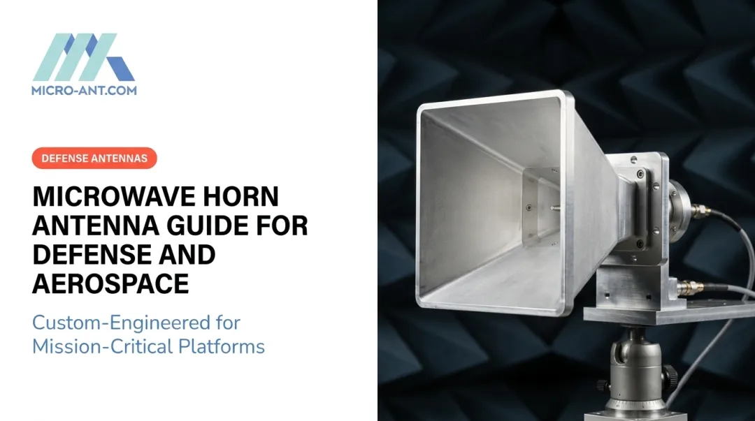
A conical horn antenna is a flared, cone-shaped waveguide extension. It transitions electromagnetic energy from a circular waveguide into free space, radiating (or receiving) that energy in a smooth, symmetrical pattern. It's built directly onto cylindrical waveguide systems, which is what gives it that rotationally symmetric aperture.
Conical horns belong to the broader horn antenna family, alongside pyramidal, sectoral, and exponential designs. What sets them apart is geometry: while a pyramidal horn flares from a rectangular waveguide into a rectangular aperture, the conical horn keeps everything round. That single distinction drives most of its practical advantages.
Core Components and Structure
Every conical horn breaks down into three functional parts:
- Feed/waveguide throat – A short section of circular waveguide, typically sized to support the TE11 mode, that connects the horn to the rest of the RF chain.
- Flared conical section – The expanding cone that gradually transforms the waveguide's confined field into a free-space-compatible wavefront.
- Open aperture – The circular opening at the horn's mouth, where the actual radiation into free space occurs.
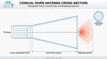
Because the aperture is circular rather than rectangular, the horn naturally accommodates two orthogonal field orientations. That circular symmetry is what allows conical horns to support circular polarization, something a rectangular pyramidal horn simply isn't built for without added complexity.
How It Works: From Waveguide to Free Space
An abrupt open waveguide end reflects a portion of the signal back down the line, creating standing waves and impedance mismatches. The flare fixes this. By gradually widening the cross-section, it matches the waveguide's impedance to that of free space, letting energy exit cleanly instead of bouncing back.
There's a tradeoff, though. As the flare angle increases, so does phase error across the aperture, since path lengths from the throat to different points on the aperture edge start to diverge. Engineers manage this with what's called the "optimum horn" design, which balances gain against horn length.
The standard formula, verified in IEEE antenna engineering literature, is:
d = √(3λρ₀)
Here, d is the aperture diameter, λ is wavelength, and ρ₀ is the horn's slant length (not simply its axial length). This relationship yields a normalized phase error of 0.375, a sweet spot antenna engineers have relied on for decades. It lets designers size a horn for a target gain without making it unnecessarily long or heavy (Aboserwal and Balanis, IEEE).
Key Technical Characteristics That Matter for Mission-Critical Systems
Gain, Directivity, and Beamwidth
Conical horn gain scales with aperture diameter relative to wavelength, but not in a straight line. As the earlier phase-error tradeoff shows, a bigger aperture doesn't automatically mean better performance if the flare geometry isn't optimized.
In practice, manufacturers offer conical horn families across a 10 to 25 dBi nominal gain range. For example, X-band models built for 8.2–12.4 GHz commonly come in 10 dBi and 15 dBi variants, with the 10 dBi unit showing roughly 59° E-plane and 58° H-plane beamwidths, narrowing considerably at 15 dBi (Mi-Wave Series 262 documentation).
For an optimum-design conical horn, aperture efficiency lands around 51–52%, depending on which phase model you're using. That efficiency figure matters for space- and weight-constrained platforms:
- Higher aperture efficiency means a smaller horn can hit a target gain.
- Lower efficiency means engineers need a larger aperture, adding mass and volume.
- The tradeoff directly affects mounting, structural loading, and integration on airborne or shipboard platforms.
Bandwidth and Frequency Coverage
Because horn antennas don't rely on resonant elements the way patch or dipole designs do, they naturally support wide operational bandwidths. This matters for multi-mission platforms that need to cover more than one frequency allocation without swapping hardware.
Micro-Ant's Ultra-Wide Band Ka Antenna System takes this a step further. It delivers 3.5 GHz of usable bandwidth within the Ka-band spectrum, extending coverage well beyond what a fixed-band feed can offer. Recognized by the Satcoms Innovation Group with a "Most Innovative" award, the system supports connectivity across multiple satellite operators without a hardware swap.
Polarization and Symmetry Advantages
Circular symmetry alone doesn't create circular polarization. The horn still needs a polarizer or feed network to establish the correct phase relationship between orthogonal modes.
Once that excitation is in place, the conical geometry supports it cleanly. That's exactly why circular polarization shows up so often in SATCOM and GNSS feed designs.
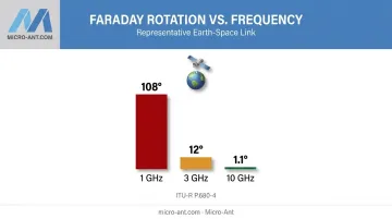
That matters because signal degradation from satellite spin and Faraday rotation can add up fast with linear polarization. ITU-R data puts Faraday rotation at roughly 108° at 1 GHz, dropping to 12° at 3 GHz and just 1.1° at 10 GHz for a representative Earth-space case (ITU-R P.680-4). Circular polarization sidesteps most of that loss.
Conical horns also produce predictable, uniform sidelobe behavior. On a crowded platform like a ship deck or aircraft fuselage bristling with antennas, that predictability simplifies interference management considerably.
Why Defense and Aerospace Programs Rely on Conical Horn Antennas
Horn antennas saw major development during WWII, when microwave and waveguide technology exploded alongside radar research. Conical designs carried that legacy forward, particularly once circular polarization became standard for satellite links.
A few things keep them in the specification sheet today:
- No moving or resonant parts. Fewer components mean fewer failure points, a critical advantage on platforms enduring constant vibration and shock, from fighter jets to missile systems to ship hulls in heavy seas.
- Natural fit for SATCOM feeds. A circular aperture pairs directly with the circular waveguide feed systems common in satellite ground and airborne terminals, minimizing transition losses.
- Phase-center stability for GNSS. Precision navigation antennas need consistent phase centers to hit millimeter-level accuracy. Micro-Ant's proprietary high-precision GNSS antenna designs build on this principle for applications where positioning error isn't an option.
- Standard-gain reference use. Conical horns still serve as calibrated gain standards in radio astronomy, deep-space communication, and radar calibration work, because their performance is well characterized and repeatable.
Primary Applications Across Defense and Aerospace Missions
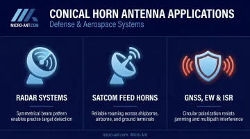
Conical horns appear across a wide range of defense and aerospace mission types, each drawing on a slightly different combination of the characteristics above.
- Radar systems – Search, tracking, and fire-control radars rely on the horn's symmetrical beam pattern for accurate, repeatable target detection, avoiding the skew an asymmetric aperture would introduce, even under heavy clutter.
- SATCOM feed horns – Shipborne, airborne, and ground terminals use conical feeds for roaming connectivity across commercial and military satellite constellations, especially as operators expand into LEO and MEO orbits.
- GNSS, precision navigation, EW, and ISR – Circular polarization and wide bandwidth preserve signal integrity through jamming environments, multipath interference, and rapid changes in platform orientation.
Engineering and Manufacturing Considerations for Extreme Environments
Getting a conical horn's geometry right is only part of the job. Material selection and qualification testing determine whether it survives the mission.
Material tradeoffs typically come down to three options:
- Aluminum – Lightweight and cost-effective, a common default for airborne applications where mass budget matters.
- Brass – Excellent RF conductivity, often used where electrical performance outweighs weight concerns.
- Composites – Increasingly common in space-qualified hardware, where thermal expansion behavior and weight savings can outweigh the added manufacturing complexity.
Material choice affects thermal expansion, which impacts dimensional stability and RF performance across the operating range. A horn that performs beautifully on the bench but drifts out of spec at altitude isn't fit for the mission.
That's why environmental qualification testing against vibration, thermal cycling, and shock standards isn't optional for defense and aerospace hardware. Simulation can only predict so much. Only hardware that survives a decade of field deployment proves the design actually works.
Micro-Ant addresses this with in-house spherical and planar near-field test chambers covering 750 MHz to 40 GHz. Keeping qualification testing domestic and in-house shortens turnaround time considerably compared to shipping hardware out for third-party testing, which directly reduces program schedule risk.
Choosing the Right Conical Horn Antenna Manufacturing Partner
Not every antenna shop is equipped to support a defense or aerospace program. Before signing a contract, a few credentials should be non-negotiable:
- AS9100:2016 and ISO 9001:2015 certification – These confirm a quality management system built specifically for aerospace and defense manufacturing standards.
- CAGE code registration – Required for direct government contracting relationships.
- Proven satellite and defense customer experience – Look for a track record with recognized operators and agencies, not just marketing claims.
Micro-Ant brings more than 20 years of bespoke antenna design experience to this space. Its testing team is well versed in the certification and compliance documentation required by major satellite operators and defense customers, including Intelsat, Inmarsat, Iridium, Eutelsat, Thuraya, and ARSTRAT.

The company's Jacksonville, Florida facility handles design, manufacturing, and testing under one roof. This keeps custom conical horn programs moving without the delays that come from juggling multiple vendors.
If your program needs a conical horn antenna built around specific frequency, gain, or environmental requirements, Micro-Ant's engineering team can help. They'll walk through the design tradeoffs before a single part gets machined.
Frequently Asked Questions
What is a conical horn?
A conical horn is a cone-shaped waveguide flare connected to a circular waveguide. It radiates or receives electromagnetic waves in a smooth, symmetrical beam pattern, making it a common choice for radar and satellite feeds.
What is the difference between a conical horn and a pyramidal horn antenna?
Conical horns have a circular, rotationally symmetric aperture suited to circular polarization. Pyramidal horns flare from a rectangular waveguide into a rectangular aperture, which suits linear polarization instead.
What is the gain of a conical horn antenna?
Gain depends on aperture diameter relative to wavelength, typically falling between 10 and 25 dBi for standard product families. The exact figure varies with the specific design and flare geometry.
Why do satellite communication systems use conical horn feeds?
Their circular symmetry supports circular polarization once paired with the right feed network, which reduces signal loss from satellite spin, orientation changes, and Faraday rotation in the ionosphere.
What frequency ranges can conical horn antennas support?
Horn antennas generally cover broad bandwidths without resonant elements, with the exact range set by waveguide diameter and flare design. Micro-Ant's Ultra-Wide Band Ka Antenna System pushes this further, delivering 3.5 GHz of continuous bandwidth within Ka-band to support roaming across multiple satellite operators.
What certifications should a defense-grade antenna manufacturer hold?
Look for AS9100:2016 and ISO 9001:2015 certification along with an active CAGE code registration. Together, these indicate a manufacturer is equipped to meet government and aerospace procurement requirements.