Introduction
Phased array antennas now power some of the most demanding systems on the planet — from Starlink's LEO satellite internet and 5G base stations to F-35 fire control radar and autonomous vehicle collision avoidance. The global phased array antenna market sits at $3.1 billion in 2024, forecast to reach $5.3 billion by 2030 at a 9.4% CAGR. That growth reflects how broadly this technology has moved beyond niche military hardware.
As adoption accelerates across defense, SATCOM, and commercial 5G, the pressure to specify these systems correctly has never been higher. For engineers, defense contractors, and SATCOM operators, understanding the underlying technology takes more than a spec sheet. What exactly is a phased array antenna? How does beamforming work? What distinguishes an AESA from a PESA?
This guide answers those questions directly: definition, operating principles, array types, applications, and key advantages — everything you need to make informed design and sourcing decisions.
Key Takeaways
- A phased array antenna steers a high-gain radio beam electronically, without any mechanical movement
- Beamforming — controlling phase and amplitude at each element — is the core mechanism behind electronic steering
- The four main types are PESA, AESA, Digital Beamforming (DBF), and Hybrid Beamforming arrays
- Primary applications span SATCOM terminals, defense radar, 5G networks, automotive ADAS, and weather monitoring
- Compared to dish antennas, phased arrays deliver microsecond beam steering, eliminate mechanical failure modes, and support simultaneous multi-beam operation
What Is a Phased Array Antenna?
A phased array antenna is a computer-controlled array of individual antenna elements whose signals combine through constructive interference to form a high-gain, directional beam. That beam can be steered to any point in space without physically moving the antenna.
A Brief History
The concept dates to spring 1905, when Karl Ferdinand Braun demonstrated directional signal transmission using three antennas at the Strasbourg Institute by controlling their relative phase. Military development accelerated during World War II. Germany's MAMMUT radar used fixed antenna arrays with electrical beam steering across ±50 degrees for long-range air defense. The first large-scale operational military phased array in the US — the AN/FPS-85 — began space surveillance operations in 1969. From there, the technology expanded into commercial SATCOM, 5G infrastructure, and automotive radar.
How Phased Arrays Differ from Traditional Antennas
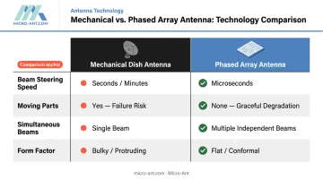
Conventional dish or reflector antennas point in one fixed direction or rely on mechanical rotation to redirect the beam. That creates three problems:
- Repositioning takes seconds or minutes with mechanical systems — too slow for fast-moving targets
- Moving parts wear out under the stress of harsh maritime or airborne environments
- A single fixed beam cannot track multiple targets or switch coverage zones simultaneously
Phased arrays eliminate all three limitations by handling beam steering electronically.
Physical Structure
Most phased arrays are planar (2D) configurations — hundreds or thousands of small antenna elements (typically microstrip patch antennas) arranged in a rectangular or hexagonal grid on a flat panel. Some designs use linear (1D) arrangements for scanning in one plane, or three-dimensional configurations for full hemispheric coverage.
Constructive and Destructive Interference
That physical arrangement is what makes phase-controlled interference possible. When each element transmits at the same frequency but with a precisely calculated phase offset, the emitted waves:
- Add together (constructive interference) in the target direction → high gain, strong signal
- Cancel out (destructive interference) in other directions → suppressed signal, reduced interference
Controlling those phase offsets in real time is what allows the beam to steer instantaneously across the full field of view.
How Does a Phased Array Antenna Work?
Beamforming: The Core Process
Beamforming controls both the phase and amplitude of the signal at every element simultaneously. By introducing calculated phase delays across the array, the combined wavefront is steered toward a target direction — no physical movement required. A central beam steering computer updates all phase shifter settings in concert, redirecting the beam in microseconds.
Key Hardware Components
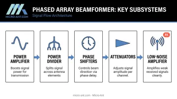
A phased array beamformer contains several critical subsystems:
| Component | Function |
|---|---|
| Power amplifier | Amplifies the source signal before transmission |
| Power divider | Splits the signal across all element channels |
| Phase shifters | Introduce precise time delays to steer the beam |
| Attenuators | Control per-element amplitude to shape the beam |
| Low-noise amplifiers (LNA) | Boost weak incoming signals on receive paths |
Beam Steering and Scanning
Beam steering sets the beam's direction using phase shifts, defined by azimuth (horizontal) and elevation (vertical) angles. Beam scanning is continuous directional movement across a coverage pattern. Advanced arrays can steer multiple simultaneous independent beams — something single-beam mechanical systems cannot do.
Sidelobes and Why They Matter
Forming a main beam also produces secondary radiation lobes (sidelobes) at other angles. Sidelobes waste transmitted power and increase susceptibility to jamming and interference. Engineers manage this through amplitude weighting — varying signal strength across elements to suppress sidelobe levels. For defense and SATCOM applications, sidelobe control is a primary design parameter. Common mitigation techniques include:
- Applying Taylor or Chebyshev amplitude windows across the element array
- Reducing edge-element excitation to taper radiation at array boundaries
- Incorporating adaptive algorithms that update weights in real time based on interference conditions
Adaptive Beamforming and Nulling
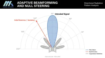
Advanced phased arrays can detect the direction of unwanted interference and place a deliberate null — a point of signal cancellation — precisely at that angle, while maintaining full sensitivity toward the intended signal. This adaptive nulling is critical for military systems operating in contested electromagnetic environments and for SATCOM terminals maintaining clean links in interference-rich spectrum.
Types of Phased Array Antennas
Passive Electronically Scanned Array (PESA)
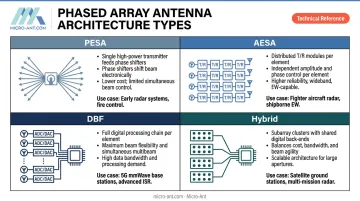
A PESA uses a single centralized transmitter/receiver shared across the entire array. The high-power signal is split via a power divider network and fed through individual phase shifters to each element.
- Advantages: cost-effective, straightforward architecture
- Limitation: one transmitter means one beam at a time
- Example use: early military radar systems, including the original AEGIS Combat System
Active Electronically Scanned Array (AESA)
AESAs place an individual transmit/receive (T/R) module at each element (or subgroup of elements). Each module contains its own power amplifier, LNA, phase shifter, and attenuator.
This distributed architecture enables:
- Multiple simultaneous beams at different frequencies
- Graceful degradation — individual element failures don't cripple the system
- Stronger jam resistance through rapid, unpredictable frequency changes
AESAs are the standard for modern fighter aircraft radar. The AN/APG-81 — the primary sensor on the F-35 — is an AESA system, providing simultaneous air-to-air and air-to-ground modes.
Digital Beamforming (DBF) Array
AESA pushed distributed architecture to the module level. DBF takes it further, placing a full digital transceiver at every element. Each element's signal is digitized and processed — typically via FPGAs — to form the antenna pattern entirely in software.
- Key advantage: effectively unlimited simultaneous independent beams
- Tradeoff: requires an RF chain per element, increasing cost and power consumption
- Applications: advanced 5G/6G base stations, next-generation LEO satellite ground terminals
In 2024, L3Harris demonstrated a DBF phased array prototype supporting up to eight simultaneous satellite contacts — compared to a traditional dish antenna that can contact only one satellite at a time.
Hybrid Beamforming Array
The hybrid approach divides the full array into subarrays. Each subarray uses analog T/R modules (like AESA), while each subarray connects to its own digital transceiver — creating clusters of simultaneous beams at lower cost and complexity than full DBF.
This architecture is the dominant practical choice for massive MIMO systems in 5G millimeter-wave networks, where full digital beamforming's hardware and power demands are too costly to deploy across thousands of base stations. Ericsson's Massive MIMO portfolio spans 16T16R to 64T64R configurations — all relying on hybrid beamforming to balance performance against cost.
Applications Across Industries
Satellite Communications (SATCOM)
Phased array antennas are the enabling technology for high-throughput satellite connectivity in Ku-band (12–18 GHz) and Ka-band (26.5–40 GHz). Their ability to electronically track LEO, MEO, and GEO satellites while maintaining stable links makes them indispensable for mobile terminals — on ships, aircraft, and defense vehicles — that can't stop to reposition a dish.
The satellite phased array antenna segment alone is projected to grow from $1.9 billion in 2024 to $8.1 billion by 2034.
Micro-Ant designs and manufactures bespoke phased array and ESA antenna solutions for these demanding SATCOM environments, serving customers including Intelsat, Inmarsat, Iridium, Eutelsat, and SES O3B mPower across defense, aviation, and maritime sectors. Their Ultra-Wide Band Ka Antenna System — recognized as Most Innovative by the Satcoms Innovation Group — covers a 3.5 GHz bandwidth within Ka-band, supporting the high data throughput modern satellite operators require.
Defense and Government
Phased array radar is the backbone of modern air defense, naval surveillance, and electronic warfare. The U.S. Navy's AN/SPY-1 radar — the sensor at the heart of the AEGIS Combat System — simultaneously performs search, tracking, and missile guidance with a track capacity exceeding 100 targets. The Space Force's AN/FPS-85 phased array can track up to 200 satellites simultaneously and detect basketball-sized objects beyond 35,000 km.
That simultaneous multi-mission capability is only possible because phased arrays can redirect their beams in microseconds — fast enough to interleave search, track, and guidance functions within a single radar timeline.
Aviation, Automotive, and Weather
Three additional application areas where phased arrays deliver distinct advantages:
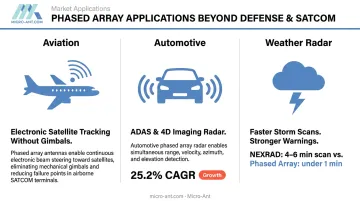
- Aviation: electronically steered antennas on aircraft maintain reliable satellite links while the platform moves, without gimbals or mechanical positioners
- Automotive: phased array radar sensors enable adaptive cruise control and collision avoidance in ADAS systems; the 4D imaging radar market is growing at 25.2% CAGR, driven by autonomous vehicle development
- Weather: NOAA's NSSL reports that conventional NEXRAD WSR-88D weather radar takes 4–6 minutes per volume scan; phased array weather radar completes the same scan in under one minute — capturing 16 images in the time NEXRAD captures two, directly extending tornado warning lead times
Emerging applications include space surveillance, radio astronomy, and RFID systems.
Key Advantages Over Traditional Antennas
Speed and Reliability
Electronic beam steering operates in microseconds — orders of magnitude faster than mechanically rotating dishes. With no moving parts, phased arrays eliminate mechanical failure modes entirely. Performance degrades gradually when individual elements fail rather than catastrophically, unlike a dish with a single-point-of-failure drive system. For defense platforms, maritime vessels, and aircraft operating continuously in harsh conditions, that graceful degradation directly preserves mission uptime.
Size, Weight, and Integration
Phased arrays built on printed circuit boards with microstrip patch elements are flat, compact, and lightweight. They mount conformally on aircraft fuselages, ship superstructures, and vehicle rooftops without aerodynamic drag penalties. Active-aperture phased array technology reduces weight, prime power consumption, and heat dissipation compared to passive systems — a critical advantage for military and aerospace platforms where size, weight, and power (SWaP) constraints directly affect mission capability.
Multi-Beam and Adaptive Capabilities
Beyond their physical footprint, phased arrays deliver operational flexibility that form-factor alone cannot explain. AESA and DBF arrays can simultaneously form and steer multiple independent beams to different targets or satellites — a capability mechanically steered single-beam systems cannot provide. Combined with adaptive nulling, this means:
- SATCOM terminals can roam across multiple satellite operators without physical repositioning
- Defense radar can simultaneously search for new threats while tracking existing ones
- Ground terminals can maintain links to LEO satellites crossing the sky at high angular rates
For mobile defense and maritime operators, this multi-beam roaming capability cuts repositioning time to zero — an outcome no dish antenna can replicate.
Frequently Asked Questions
Frequently Asked Questions
What is a phased array?
A phased array is a computer-controlled group of antenna elements that forms a steerable beam of radio waves through electronic phase shifting. The beam can be directed to any angle within the antenna's field of view without physically moving the antenna.
What is phased array NDT?
Phased array NDT (Non-Destructive Testing) applies the same phased array principle to ultrasonic sound rather than radio waves. Arrays of piezoelectric transducers with electronically controlled phase delays steer and focus ultrasonic beams through solid materials to detect internal flaws. It is a distinct application domain from RF phased array antennas.
What is the difference between AESA and PESA?
A PESA uses a single centralized transmitter shared across all elements, limiting it to one beam at a time. An AESA has individual T/R modules at each element, enabling multiple simultaneous beams and broader frequency agility, with built-in resilience to jamming and component failure.
How does beamforming work in a phased array antenna?
Beamforming introduces precise, electronically controlled phase delays to the signal at each element. The combined wavefronts add constructively in the target direction (increasing gain) and cancel destructively elsewhere, steering the beam with no physical movement required.
What frequency bands do phased array antennas operate in?
Phased arrays operate across UHF through millimeter-wave frequencies. Common bands include L, S, C, X, Ku (12–18 GHz), and Ka (26.5–40 GHz). The right band depends on the application: Ka-band suits high-throughput SATCOM, while mmWave (24–100 GHz) supports 5G deployments.
What are the main applications of phased array antennas?
The primary domains are military radar and electronic warfare, SATCOM terminals for aviation and maritime, 5G/6G base stations, automotive ADAS radar, weather radar, and space surveillance systems.