Introduction
An antenna that looks perfect on paper can still fail in the field. Gain, impedance match, and radiation pattern all need to be verified against design specs before deployment, whether that antenna is headed to a defense radar system or a maritime SATCOM terminal.
Skip proper testing and the consequences show up later: signal dropouts, failed certifications, or a costly redesign after installation. The stakes climb further at mmWave and Ka-band frequencies, where positioning tolerances shrink to roughly 1/100 of a wavelength at E-band, according to NIST's antenna measurement challenges roadmap.
This guide walks through the tools you need, three proven testing methods, how to read your results, and the common mistakes that ruin good data.
Key Takeaways
- Antenna testing confirms impedance match, gain, and radiation pattern before deployment
- Three core methods exist: VNA bench testing, far-field/anechoic testing, and near-field scanning
- VSWR, return loss, and pattern symmetry are the readings that matter most
- Calibration errors, multipath, and far-field violations cause most measurement errors
- Method choice depends on required accuracy, frequency, and budget
What You Need to Test Antennas
A quick field check and a certification-grade characterization call for very different setups. The gear you need scales with how precise your answer has to be.
Tools and Indicators Required
At minimum, testing an antenna's impedance match requires:
- Vector Network Analyzer (VNA) or handheld antenna analyzer
- Calibration kit with SOLT (Short-Open-Load-Thru) standards
- RF cables and adapters matched to the antenna's connector type
- A reference or feed antenna for radiated tests
- A positioner or rotator to sweep azimuth and elevation
- Pattern plotting software to visualize results
For deeper characterization, add a spectrum analyzer, power meter, and access to an anechoic or near-field chamber, like the spherical and planar setups Micro-Ant runs in-house across 750 MHz to 40 GHz. Full gain and pattern data simply isn't possible on a bench alone.
Preconditions and Setup
Before collecting a single data point, get the setup right:
- Calibrate the VNA immediately before testing, at the antenna's connector reference plane, to strip out cable and connector error
- Mount the antenna securely and confirm correct orientation and polarization relative to the source or probe
- Clear the environment of nearby metal objects and reflective surfaces that create parasitic echoes
- Control temperature for high-frequency stability, since thermal drift shifts both phase and mechanical dimensions
- Verify test distance meets far-field (Fraunhofer) requirements before running any radiated measurement
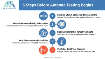
Skip step one and every reading that follows carries the same systematic error, no matter how careful the rest of the test is.
Methods to Test Antennas
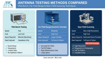
Method choice depends on the accuracy you need, the frequency range involved, and what your budget allows. Bench checks are fast and cheap. Full characterization is neither, but it's what certification demands.
Method 1: VNA-Based Bench Testing (VSWR & Return Loss)
This method measures impedance match and reflected power, confirming the antenna is properly matched to its feedline at the target frequency. It's the fastest, lowest-cost check available.
Tools needed: VNA, calibration kit, RF cable, matched load
Steps:
- Calibrate the VNA using SOLT standards at the antenna's connector reference plane
- Connect the antenna and sweep across the full operating frequency band
- Record VSWR/return loss values and compare against datasheet specifications
Pros: Fast, inexpensive, ideal for field checks and incoming inspection.
Cons: Tells you nothing about radiation pattern, gain, or polarization performance. A perfectly matched feed can still radiate poorly.
Method 2: Far-Field Range / Anechoic Chamber Testing
Far-field range testing is where you actually see how the antenna radiates. The antenna under test (AUT) sits at a calibrated distance from a reference antenna while gain, beamwidth, and pattern are captured directly.
Tools needed: Anechoic chamber or open-air range, positioner, reference antenna, VNA or receiver
Steps:
- Confirm test distance meets the Fraunhofer far-field criterion for the AUT's aperture size and frequency
- Rotate the AUT through azimuth and elevation, recording signal strength at each angle
- Plot the radiation pattern and compare peak gain against expected values
The routine far-field boundary follows R ≥ 2D²/λ, where D is the largest aperture dimension and λ is wavelength, according to NIST's near-field scanning theory documentation. For a large reflector antenna at Ku-band, that distance can stretch well beyond what a typical lab can accommodate.
Pros: Full pattern and gain data in one pass.
Cons: Requires significant physical space or a dedicated chamber, making it expensive for occasional use.
Method 3: Near-Field Scanning (Planar/Spherical)
Near-field scanning measures the electromagnetic field close to the antenna, then mathematically transforms that data to predict far-field performance. It's especially valuable for high-gain or high-frequency antennas where a true far-field range would be impractically large.
Tools needed: Near-field probe, precision scanner/positioner, transform software
Steps:
- Position the AUT and scan a planar or spherical surface at the prescribed probe spacing
- Capture amplitude and phase data across the full scan surface
- Apply Fourier or spherical harmonic transforms to derive far-field gain and pattern
Pros: Highly accurate across wide frequency bands and needs far less physical space than a far-field range.
Cons: Demands specialized equipment and transform software; not something you set up on short notice.
This is exactly why Micro-Ant operates spherical and planar near-field chambers spanning 750 MHz to 40 GHz at its Jacksonville, Florida facility. Engineers get certification-grade results without shipping hardware overseas or waiting weeks for a slot at an outside range.
How to Interpret the Results
Misreading test data is its own failure mode. Ship a non-compliant antenna, or worse, miss an actual hardware defect, and you're looking at a field failure down the line instead of a fast fix on the bench.
Here's how to sort your results into next steps:
| Result Category | What You'll See | What to Do Next |
|---|---|---|
| Normal | VSWR below 2:1 (return loss better than -10 dB); pattern and gain within typical tolerance of datasheet | Proceed with integration or deployment |
| Minor Issue | VSWR between 2:1–3:1 or gain within 1 dB of spec | Reseat connectors, re-calibrate, retest before flagging a fault |
| Out-of-Spec | VSWR above 3:1, unexpected pattern nulls, or gain well below spec | Inspect physically; consult the manufacturer or a testing lab |
Thresholds and Units Aren't Always What They Seem
2:1 VSWR isn't a universal pass/fail line. It's a common commercial benchmark, but interface specifications can be tighter. Military SATCOM terminal standards, for instance, sometimes require VSWR as low as 1.25:1. Always check the governing spec for your application rather than assuming a generic number applies.
Return loss and VSWR describe the same physical reality from two angles: VSWR 2:1 corresponds to a return loss of 9.54 dB, commonly rounded to "10 dB" in casual conversation. Know the convention your test report uses before comparing it against a spec sheet.
Common Errors in Testing Antennas
Most bad antenna data traces back to one of five recurring mistakes:
- Skipping or rushing VNA calibration: introduces systematic error into every subsequent reading, no matter how careful the rest of the setup is
- Testing inside the far-field boundary: produces distorted gain and pattern data because residual phase curvature hasn't flattened out yet
- Ignoring multipath reflections: nearby metal structures, walls, or test fixtures scatter energy back into the measurement and corrupt readings
- Misaligning polarization: a mismatched AUT and reference antenna produces falsely low gain readings that look like a hardware defect
- Using the wrong method for the job: relying on bench VSWR checks alone when a certification actually requires full pattern and gain data
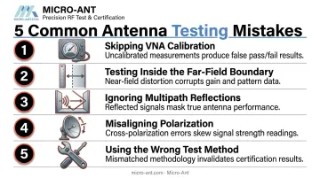
Each of these is avoidable through disciplined test procedure. Correcting them is often the difference between a clean test report and a week spent chasing a phantom problem.
Safety and Best Practices
Good testing habits protect people as much as data quality.
- Observe RF exposure limits. The FCC caps occupational exposure at f/300 mW/cm² (300–1500 MHz) and 5 mW/cm² (1500 MHz–100 GHz), averaged over six minutes, per 47 CFR § 1.1310.
- Maintain safe distance from actively transmitting antennas during range tests.
- Use ESD and grounding precautions when handling sensitive feed components, especially on high-gain or phased-array assemblies.
- Keep calibration standards current. Equipment drift is silent, and it corrupts data long before anyone notices.
- Maintain a stable test environment. Temperature swings and inconsistent line of sight undermine repeatability, even with perfect equipment.
These habits cover day-to-day testing, but certification-required programs demand a further layer of scrutiny. For antennas headed into those applications, partnering with an ISO 9001:2015 or AS9100:2016-certified facility adds an audited layer of process control. Micro-Ant runs its testing operations under both certifications, producing certification-ready test reports for satellite operators and defense customers without an added qualification step on the customer's end.
Conclusion
Accurate antenna testing protects performance, safety, and compliance before anything ships. Reliable results come from pairing the right method with the precision your application demands, then backing it up with careful calibration and environmental control.
Correct interpretation points straight to the next step: deploy, adjust, or repair. Miss that call, and problems surface in the field instead of the lab, often at a much higher cost—Micro-Ant's in-house chambers help catch them first.
Frequently Asked Questions
What is the difference between near-field and far-field antenna testing?
Far-field testing measures radiation directly at a distance meeting the Fraunhofer criterion. Near-field testing measures close to the antenna and mathematically transforms the data to predict far-field performance, often in far less physical space.
How do I know if my antenna is properly matched?
A VSWR below 2:1, or return loss better than -10 dB at the operating frequency, generally indicates a well-matched antenna. Verify this with a calibrated VNA at the connector reference plane.
What equipment do I need to test an antenna at home or in the field?
A basic antenna analyzer or VNA with a calibration kit handles VSWR and return loss checks. Pattern and gain measurements, though, require access to a chamber or open-air range.
Can I test an antenna without an anechoic chamber?
Yes, for impedance and VSWR checks on a bench with a VNA. Accurate gain and pattern data, however, require a controlled facility — manufacturers like Micro-Ant run in-house near-field chambers spanning 750 MHz to 40 GHz specifically for this purpose.
How often should antennas be tested?
Test after installation, after any physical damage or environmental exposure, and on a maintenance schedule for mission-critical defense or satellite applications. There's no single universal interval; it's program- and event-driven.
What does VSWR tell you about antenna performance?
VSWR quantifies how much power reflects back due to an impedance mismatch. Lower values mean more efficient power transfer from the feedline into the antenna itself.