Traditional resonant antennas like dipoles or patches choke on this problem. Their bandwidth is tied to a specific wavelength, so covering a wide frequency range means stacking multiple elements or accepting compromised performance.
The spiral antenna solves this differently. Its geometry is frequency-independent, meaning the same physical structure can operate across a decade or more of bandwidth without changing shape or size. That property alone explains why spiral antennas remain the go-to choice for SIGINT, direction-finding, and multi-band SATCOM systems more than 60 years after their invention.
This guide breaks down how ultra-wideband (UWB) spiral antennas work, the major design variants, where they're deployed today, and what to evaluate before sourcing one for a mission-critical program.
Key Takeaways
- Spirals hold near-constant impedance and radiation patterns across extreme bandwidth ratios
- Archimedean, logarithmic, and cavity-backed spirals suit sensing, EW, and receiver missions
- Circular polarization makes spirals ideal for GNSS, SATCOM, and multipath rejection
- Low per-element gain is the primary trade-off, often solved through arraying
- Platform constraints and ruggedization standards should guide antenna selection early on
What Is an Ultra-Wideband Spiral Antenna?
Spiral antennas belong to a class known as frequency-independent antennas, first developed in the 1950s. Victor Rumsey at the University of Illinois formulated the underlying principle: if an antenna's shape is defined entirely by angles rather than fixed lengths, scaling the wavelength doesn't change its electrical geometry.
J.D. Dyson turned that principle into a working design between 1955 and 1957, building the first equiangular spiral.
That self-scaling geometry is why a single spiral can "look the same" electrically at 2 GHz and 15 GHz. There's no resonant length to outgrow, which removes the bandwidth ceiling that limits dipoles and patches.
Basic Construction
A typical spiral antenna consists of:
- Two (or more) conductive arms winding outward from a central feed point
- Arms etched or printed on a dielectric substrate, similar to microstrip antenna fabrication
- A feed region at the center driving the arms in phase quadrature to generate circular polarization
Real spirals aren't infinite, though. Physical size sets the practical limits: outer diameter determines the lowest usable frequency, while the center feed region sets the highest.
Design literature recommends roughly 20% margin on diameter to reduce truncation effects at the low end. This is why bandwidth should always be described with a specific criterion (VSWR, axial ratio, or gain) rather than an unlimited claim.
Polarization Behavior
Spiral antennas transmit circularly polarized waves. In receive mode, they pick up linearly polarized signals from any orientation while rejecting circularly polarized signals of the opposite sense. That selectivity matters enormously for GPS/GNSS and satellite links, where multipath reflections often arrive with reversed polarization sense.
One trade-off engineers must accept: spiral antennas typically deliver low gain per element. The active radiating region stays roughly one wavelength in circumference regardless of frequency, so gain stays relatively flat instead of climbing with aperture size. This is precisely why spirals frequently appear in arrays when a program needs higher directivity.
Spiral Antenna Design Principles and Common Types
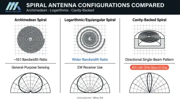
Every spiral variant follows the same frequency-independence principle, but arm geometry, bandwidth ratio, and radiation behavior differ enough that type selection becomes mission-specific.
Archimedean Spiral
The Archimedean spiral uses constant arm spacing, meaning the radius increases linearly with angle rather than exponentially. This produces a design with moderate, well-documented bandwidth: NIST's foundational survey of frequency-independent antennas reports stable Archimedean behavior up to approximately 10:1 bandwidth ratios.
It's not perfectly self-scaling in the strict Rumsey sense, but measured designs retain broadband impedance and pattern performance alongside circular polarization. That combination of simplicity and reliable coverage makes it a popular baseline for general-purpose wideband sensing applications.
Logarithmic (Equiangular) Spiral
The logarithmic, or equiangular, spiral expands exponentially rather than linearly. Its arms maintain a constant angle relative to the radius vector, which is the geometry Dyson originally used to demonstrate true self-scaling behavior.
This exponential expansion typically achieves an even wider bandwidth ratio than the Archimedean form. That extra headroom is why equiangular spirals show up so often in electronic warfare (EW) receivers, where continuous multi-octave coverage matters more than compact size.
Cavity-Backed Spiral
An unbacked planar spiral radiates from both faces, with opposite handedness on each side. That bidirectional pattern isn't ideal when a program needs a single directional beam.
Adding a cavity behind the spiral suppresses that back-lobe radiation and improves front-to-back ratio. This design is common in aircraft skin-mounted and conformal installations.
L3Harris's Q180 series is a fielded example of this approach, delivering cavity-backed coverage across 1–18 GHz. Micro-Ant applies the same cavity-backed approach in custom EW and direction-finding antennas, tuning cavity depth and absorber loading to each platform's frequency range.
The trade-off: absorptive cavity material reduces efficiency and gain slightly in exchange for that pattern control. Shallow cavities below roughly one-quarter wavelength typically need absorber loading to manage internal reflections, further constraining the efficiency-versus-profile balance.
Beyond single-beam control, cavity-backed spirals also support direction finding through multi-arm configurations. Four-arm designs, for example, generate N-1 distinct modes whose magnitude and phase vary predictably with arrival direction. That modal behavior is the foundation for direction-finding accuracy, discussed next.
Key Applications of UWB Spiral Antennas
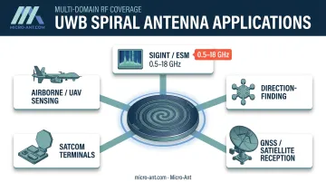
UWB spiral antennas power five demanding applications, from electronic warfare to satellite roaming, each drawing on the same broadband, circularly polarized design.
SIGINT and Electronic Support Measures
Wideband spiral arrays enable continuous spectrum monitoring across multi-octave ranges. Fielded EW/ESM systems commonly span:
- 0.5–2 GHz for lower-band intercept
- 1–18 GHz for broad multi-octave coverage
- 2–18 GHz for high-band characterization
These ranges, chosen by mission profile and platform, let a single aperture intercept and characterize signals across an enormous swath of spectrum without antenna switching.
Direction-Finding Systems
Multi-arm spiral configurations compare amplitude and phase across elements to estimate emitter bearing. This modal approach traces back to early phase-comparison DF work using two-wire Archimedean spirals, refined over decades into calibrated four-arm systems used in modern monopulse DF receivers.
GNSS and Satellite Reception
Right-hand circularly polarized (RHCP) spiral elements are standard for GPS/GNSS antennas because GPS signals are transmitted as RHCP by specification. Matching that polarization maximizes signal coupling while naturally discriminating against multipath reflections, which often arrive reversed in sense.
Micro-Ant applies this same broadband circular-polarization engineering discipline in its proprietary high-precision GNSS antenna designs, built for millimeter-level accuracy across multiple satellite constellations.
SATCOM Ground and Mobile Terminals
The same UWB design philosophy that drives spiral antenna development extends to Micro-Ant's award-winning Ultra-Wide Band (3.5 GHz) Ka Antenna System, which earned the "Most Innovative" award from the Satcoms Innovation Group.
This system allows connectivity across extended Ka-band frequencies, letting terminals roam between multiple satellite operators without hardware changes — a capability increasingly valuable as LEO and MEO constellations multiply.
Airborne and UAV Sensing Platforms
Compact, low-profile spiral geometry fits naturally into space-constrained aircraft, UAV, and vehicular installations. Conformal mounting reduces drag and radar cross-section compared to protruding antennas, a meaningful advantage on airframes where every added surface feature carries a performance penalty.
Advantages and Trade-offs of Spiral Antenna Technology
Spiral antennas offer real advantages, but engineers should weigh them against two consistent trade-offs.
Where spirals win:
- Unmatched bandwidth-to-size ratio compared to horn, log-periodic, or biconical antennas
- True multi-band, multi-mission functionality from a single aperture
- Reliable circular polarization across the full operating band
Where spirals require compensation:
- Low per-element gain: the active region holds roughly one wavelength in circumference, so gain doesn't scale with antenna size; arraying or added amplification typically closes this gap for long-range links.
- Axial ratio degradation off boresight: polarization purity peaks near boresight, but wide scan angles unbalance the field via pattern geometry and cavity effects. Account for this in link budgets rather than assuming uniform polarization across the full field of view.
Design Considerations for Selecting a UWB Spiral Antenna
Choosing the right spiral antenna starts well before evaluating vendors. Three questions should shape the requirement:
- What frequency range and bandwidth ratio does the mission actually need? Broadband EW coverage calls for a very different design than a narrower defense communications band. Defining this early prevents over-engineering (and overpaying) for bandwidth the program will never use.
- What are the platform's physical constraints? Aircraft, UAVs, ground vehicles, and maritime installations each impose different mounting profiles. Conformal or low-profile requirements often push the design toward cavity-backed or planar configurations.
- What environmental ruggedization does the deployment demand? Vibration, temperature extremes, and salt fog exposure are standard concerns for defense and maritime programs. MIL-STD-810H sets the environmental test methods, but "MIL-STD tested" means nothing without specifying which procedures and levels applied.
Getting these three answers locked down before design work begins saves significant rework later in the program.
Why Partner with Micro-Ant for Bespoke UWB Spiral Antenna Solutions
Spiral antenna performance lives or dies on validation. Micro-Ant operates in-house spherical and planar near-field test chambers covering 750 MHz to 40 GHz, built specifically for characterizing broadband antenna behavior across the full spiral operating range, not just spot-checking a few frequencies.
That testing infrastructure operates within certified, vertically integrated facilities:
- AS9100:2016 and ISO 9001:2015 certified operations in Jacksonville, Florida
- More than 20 years of antenna design and manufacturing experience
- Every unit validated under the same roof where it was built
Micro-Ant backs its engineering claims with industry recognition. The company's Ultra-Wide Band (3.5 GHz) Ka Antenna System won the 2022 Innovation of the Year Award from the Satcoms Innovation Group, recognizing genuine progress in pushing bandwidth boundaries for SATCOM terminals.
For defense, aerospace, SATCOM, and maritime clients, Micro-Ant builds bespoke antennas rather than pulling from a generic catalog. Combined with US-based rapid testing, that approach reduces program risk and shortens development timelines: critical advantages when a spiral antenna needs to work the first time, in the field, under mission conditions.

Frequently Asked Questions
What frequency range can a spiral antenna cover?
Bandwidth ratio depends heavily on spiral type and physical size. Common defense and EW spiral antennas span roughly 1–18 GHz or more, but the exact range depends on the specific design, so confirm it directly with your manufacturer.
What is the difference between an Archimedean and a logarithmic spiral antenna?
Archimedean spirals use constant arm spacing and deliver moderate bandwidth, typically around 10:1. Logarithmic (equiangular) spirals expand exponentially, achieving wider bandwidth ratios that make them common in EW receivers requiring multi-octave coverage.
Why are spiral antennas circularly polarized?
The rotational arm geometry naturally generates circular polarization as energy radiates from the active region. This is why GPS/GNSS and satellite applications favor spirals, since circular polarization helps reject multipath interference.
What is a cavity-backed spiral antenna used for?
A backing cavity suppresses unwanted back-lobe radiation, improving front-to-back ratio for a more directional aperture. This makes cavity-backed designs well-suited to aircraft skin-mount and conformal installations where a single-direction beam is required.
Are spiral antennas suitable for direction-finding applications?
Yes. DF systems widely use multi-arm spiral configurations because they support multiple distinct modes, each with direction-dependent amplitude and phase that calibrated systems can translate into bearing estimates.
How do I choose the right ultra-wideband spiral antenna for my program?
Start by defining frequency range, platform constraints, and ruggedization requirements. From there, work with an experienced manufacturer like Micro-Ant to custom-engineer and test a solution matched to those specifics.