Whether you're designing telemetry links for a CubeSat or a ruggedized comms array for a field radio, the same core tension shows up: gain versus size, bandwidth versus footprint, performance versus survivability. Engineers can't have everything at once, and every platform, from LEO smallsats to shipboard terminals, comes with its own set of constraints.
This guide breaks down the S-band spectrum, the antenna architectures built for it, the design parameters that separate a good antenna from a failed link budget, and the common engineering headaches that come with the territory.
Key Takeaways
- S-band (2-4 GHz) powers satellite TT&C, defense comms, weather radar, and mobile satcom.
- Patch, helix/turnstile, and wideband array architectures each solve different mission problems.
- Gain, beamwidth, and polarization decisions must trace back to a real link budget, not guesswork.
- Bespoke engineering usually outperforms catalog antennas under ruggedization or dual-band demands.
Understanding the S-Band Spectrum and Its Applications
S-band covers 2-4 GHz under the ITU's radar-letter convention, sitting right at the boundary where UHF (300 MHz-3 GHz) hands off to SHF (3-30 GHz). That means S-band isn't purely an "upper microwave" band. Part of it technically still falls in UHF territory, which matters when you're cross-referencing regulatory filings or legacy hardware specs.
The band has real regulatory history behind it. The FCC adopted S-band spectrum for satellite Digital Audio Radio Service back in January 1995, following the WARC-92 allocation. NASA has also relied on S-band for decades, using it for Space Shuttle air-to-ground voice links and for International Space Station command-and-control communications.
That NASA and NOAA legacy has made S-band attractive to a newer generation of operators. Smaller satellites gravitate toward the band, though not because it's unregulated.
Every non-federal U.S. spacecraft transmitter still needs FCC licensing (or NTIA authorization for government missions). What S-band avoids is the added baggage of amateur-band rules, like open, unencrypted telemetry requirements and IARU coordination, that come with VHF/UHF amateur allocations. This simplifies licensing pathways rather than removing federal oversight.
Key Applications Driving S-Band Antenna Demand
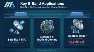
Three use cases dominate S-band antenna demand:
- Satellite TT&C: The NTIA designates 2200-2290 MHz primarily for spacecraft tracking, telemetry, and control, spanning space-to-Earth and space-to-space links across LEO, MEO, and GEO missions.
- Defense and tactical communications: NTIA has confirmed that mobile satellite service bands below 3 GHz support U.S. military operations worldwide, making S-band a workhorse for MSS-based field connectivity.
- Weather radar: NOAA's WSR-88D network runs 159 radars across the 2700-3000 MHz range, each using an 8.53-meter dish to deliver 45.5 dB of gain and a 0.925-degree beamwidth at 2850 MHz.
Types of S-Band Antennas and Their Design Approaches
Not every mission needs the same antenna. Coverage requirements, mounting constraints, and orientation stability all push designers toward different architectures.
Patch (Microstrip) Antennas
Patch antennas dominate small satellite and space-constrained platforms because they're flat, light, and easy to integrate into a spacecraft panel or field unit housing. But there's no universal "correct" size. Published 2.4-2.45 GHz designs vary considerably:
| Design | Frequency | Patch Size | Performance |
|---|---|---|---|
| FR4-substrate patch | 2.4 GHz | 38 x 29 mm | 5.53 dB simulated gain |
| Inset-fed patch | 2450 MHz | 33.69 x 41.75 mm | 2381-2433 MHz resonance, ~43-50 MHz bandwidth |
Exact dimensions depend on substrate permittivity, thickness, and target frequency. Treat "40-50 mm square" as a starting concept, not a spec sheet.
Polarization matters just as much as size. LHCP and RHCP are orthogonal circular states, and the choice has to match the link interface, not the frequency band itself.
Feed offset design (specifically the inset gap width) directly shifts where patch input resistance matches the feedline impedance. On thin, low-loss substrates, small changes in that inset-gap ratio can noticeably shift both bandwidth and resonant frequency, which is why feed geometry deserves as much attention as patch dimensions.
Helix and Turnstile Antennas
When a satellite's orientation isn't fixed relative to the ground station, patch antennas struggle. Helix and turnstile designs solve this by delivering omnidirectional coverage with consistent circular polarization, regardless of spacecraft attitude.
Turnstile antennas use orthogonal radiating elements with quadrature excitation to generate circular polarization across a hemispheric field of view. Quadrifilar helix designs achieve a similar effect using four symmetrically wound conductors.
Both approaches work well for TT&C uplink and downlink, but gain, axial ratio, and pattern nulls all shift once the antenna is mounted on an actual spacecraft body. Installed-platform verification isn't optional here.
Wideband and Phased Array Configurations
Fixed patch antennas lock you into a narrow allocation. Wideband designs give operators frequency flexibility across multiple satellite systems without a redesign every time a mission shifts frequency plans.
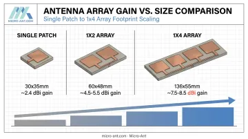
Array configurations push this further, trading size for gain. A 2022 peer-reviewed study tracked this tradeoff directly:
| Configuration | S-band overlap | Realized gain | Footprint |
|---|---|---|---|
| Single patch | 2.5-4.0 GHz | ~2.4 dBi | 30 x 35 x 1.6 mm |
| 1x2 array | 3.3-4.0 GHz | ~4.5-5.5 dBi | 60 x 48 x 1.6 mm |
| 1x4 array | 2.4-4.0 GHz | ~7.5-8.5 dBi | 136 x 55 x 1.6 mm |
That 1x4 array roughly tripled the footprint of the single patch while more than tripling gain, but it also introduced corporate-feed loss, tighter fabrication tolerances, and mutual coupling between elements. Bigger apertures aren't automatically better. They're a deliberate tradeoff that has to match the mission's mass and volume budget.
Critical Design Parameters for S-Band Antenna Engineering
Every S-band antenna decision traces back to five interlocking parameters. Get one wrong, and the rest of the design compensates poorly.
Frequency range and bandwidth. A mission targeting the 2.2-2.29 GHz TT&C downlink needs a different design than one built for a broader 2.0-2.4 GHz allocation. Narrow the frequency plan first, since everything else follows from it.
Gain versus beamwidth. These two move in opposite directions: higher gain means a narrower beam, which means tighter pointing requirements. The right balance comes from the link budget, not a preference for "more gain is always better."
Polarization selection. Circular polarization resists multipath fading and tolerates orientation drift, which is why it dominates satellite links. Linear polarization can work for fixed, well-aligned ground-to-ground links, but it's far less forgiving on a rotating or tumbling platform.
Mass, size, and environmental limits. Space and field hardware both face harsh constraints:
- ESD protection matters for polar-orbit missions with heavy charged-particle exposure, though grounding and handling precautions during integration remain necessary even on ESD-protected interfaces.
- Published S-band flight hardware operating ranges vary by product, with one TT&C antenna spec sheet listing -20°C to +60°C while others use narrower ranges.
- Confirm the specific product's thermal qualification rather than assuming a universal figure.
Impedance matching and feed design. Microstrip feed offset placement and connector selection determine how cleanly power transfers from the transmitter to the radiating element. Get the feed geometry wrong, and you'll see it immediately in VSWR and return loss measurements.
Common Design Challenges in S-Band Antenna Development
Three challenges show up repeatedly across S-band programs, regardless of platform.
Miniaturization versus performance. CubeSats, handheld tactical units, and space-constrained defense equipment all demand smaller antennas. But shrinking the aperture reduces gain and bandwidth. There's no way around this tradeoff. It has to be engineered around, usually through array configurations, optimized feed structures, or accepting a narrower operating band.
Co-location interference. Many platforms run S-band alongside other frequencies, most commonly S/X dual-band systems. Careful filter and port design has demonstrated real isolation gains:
- Shared-aperture designs, where an S-band antenna doubles as ground structure for an X-band array, achieve isolation better than 38 dB while maintaining 7.5 dBi S-band gain.
- Commercial X-band TT&C hardware with S-band hybrid filtering reports greater than 25 dB of suppression at X-band downlink frequencies.
These numbers are architecture-specific, not universal guarantees, but they set a useful benchmark for what's achievable.
Ruggedization standards. Defense, maritime, and land platforms face vibration, shock, and temperature extremes that space hardware doesn't. MIL-STD-810H governs environmental engineering and test tailoring for these stresses, while MIL-STD-461 covers electromagnetic interference emissions and susceptibility. Meeting both standards simultaneously, without sacrificing RF performance, is where a lot of catalog antennas fall short.

Why Partner with Micro-Ant for Custom S-Band Antenna Design
Off-the-shelf antennas rarely survive contact with a real mission's constraints. Micro-Ant has spent over 20 years engineering bespoke antenna systems for defense, aviation, maritime, and land applications. The company holds AS9100:2016 and ISO 9001:2015 certifications that satellite operators and government agencies require before they will even open a proposal.
Validation matters as much as design. Micro-Ant's in-house spherical near-field scanner covers 750 MHz to 40 GHz, comfortably spanning the full S-band range with 360° x 360° pattern coverage for certification-grade measurements. That includes:
- S-parameter testing (VSWR, return loss, insertion loss, isolation, impedance matching)
- Axial ratio and cross-polarization characterization
- Gain, directivity, and efficiency measurements across full pattern envelopes
Because this testing happens in-house at Micro-Ant's Jacksonville, Florida facility, programs avoid the scheduling delays and IP exposure that come with shipping hardware to third-party or overseas labs. The company's testing team brings over a century of combined antenna testing experience to the process.
The company's certified testing relationships already span major satcom operators and defense organizations, including Eutelsat, Intelsat, Inmarsat, SES O3B, Iridium, Thuraya, and ARSTRAT. Does your S-band program need an antenna engineered around your mission's specific gain, polarization, and environmental requirements rather than forced into a catalog spec? Reach out to Micro-Ant's engineering team to start the conversation.
Frequently Asked Questions
What is an S-band antenna?
An S-band antenna operates in the 2-4 GHz frequency range and is used for satellite tracking, telemetry and command (TT&C), Doppler weather radar, and mobile communication links. Design varies widely by architecture and mission.
What is the difference between L-band and S-band antennas?
L-band (1-2 GHz) offers a longer wavelength, better propagation, and typically needs a larger antenna aperture. S-band (2-4 GHz) delivers higher gain per aperture size and often supports higher-capacity links, though data rates ultimately depend on bandwidth and modulation.
What are the typical dimensions of an S-band patch antenna?
Published 2.4-2.45 GHz designs range from roughly 29-42 mm per side, depending on substrate material and exact target frequency. There's no fixed universal size. Actual dimensions come from the substrate's dielectric properties and the required resonant frequency.
What are common applications of S-band antennas?
S-band antennas support satellite TT&C across LEO, MEO, and GEO missions, weather and Doppler radar networks, defense and mobile satellite communications, and growing IoT/telemetry deployments.
How do I choose the right S-band antenna for my project?
Start by defining your exact frequency allocation, required gain and beamwidth from your link budget, polarization needs, and environmental exposure. These four factors narrow the field to one or two viable architectures fast.
Can S-band antennas be customized for extreme environments?
Yes. Micro-Ant engineers bespoke S-band antennas to withstand shock, vibration, and temperature extremes for defense, maritime, and land applications, often exceeding what standard catalog antennas can survive.