Introduction
Specifying an X-band system for the first time looks straightforward — until the sub-band allocations, regulatory obligations, and propagation constraints start diverging in ways a single frequency label doesn't capture. The 8–12 GHz range offers a favorable intersection of radar resolution, satellite link performance, and antenna compactness, but it is not a uniform operating environment.
Engineers and procurement professionals who treat 8–12 GHz as a uniform block routinely encounter avoidable errors: undersized link margins, unlicensed sub-band selections, and antenna designs mismatched to actual operating frequencies.
This article covers the key factors that drive those errors — and how to avoid them — including the IEEE definition and sub-band structure, propagation and antenna properties, primary application domains, and formal specification and validation requirements.
Key Takeaways
- X-band spans 8.0–12.0 GHz per IEEE Std 521-2019, with wavelengths of 2.5–3.75 cm, placing it in the SHF microwave region
- Military SATCOM uplinks (7.9–8.4 GHz) and downlinks (7.25–7.75 GHz) are adjacent allocations, not inside the IEEE radar definition
- Rain attenuation at 10 GHz reaches 0.220 dB/km at moderate rainfall: negligible at short range but a measurable link budget factor at satellite distances
- Shorter wavelengths allow compact, high-gain antenna designs — a critical advantage for shipborne, airborne, and man-portable platforms
- Specifying a system as "X-band capable" without identifying the sub-band leaves procurement, licensing, and interoperability undefined
What X-Band Frequency Represents in Radar and Satellite Systems
The IEEE Definition and Its Boundaries
IEEE Std 521-2019 — IEEE Standard Letter Designations for Radar-Frequency Bands — defines X-band as 8.0–12.0 GHz, with free-space wavelengths of 3.75 cm at 8 GHz down to 2.5 cm at 12 GHz. This is the reference used in radar engineering, defense procurement documents, and antenna manufacturer datasheets.
The band sits within the ITU's Super High Frequency (SHF) class, which covers 3–30 GHz. Below X-band lies C-band (4–8 GHz); above it is Ku-band (12–18 GHz). That position produces a practical tradeoff: better angular resolution than C or S-band for a given aperture size, and substantially better rain resilience than Ku or Ka-band at equivalent link distances.
Some communications engineering contexts reference a narrower range of approximately 7.0–11.2 GHz, but this has no verified basis in an authoritative published standard. For equipment specified against a contract or regulatory filing, IEEE 8–12 GHz is the correct reference.
That settled definition is also the starting point for understanding where the band name itself came from — and what the label actually governs in practice.
Why "X-Band" and What the Label Actually Controls
The "X" designation originated in World War II, when radar operating frequencies were labeled with letters to prevent disclosure of exact frequencies. No authoritative post-war technical meaning was ever formally assigned to the letter itself — claims that it stands for "extreme" or "cross" are folk etymologies that have circulated without a primary source.
What the band label actually governs is substantial:
- Antenna dimensions — element sizing and aperture geometry scale with wavelength
- Component selection — amplifiers, filters, and feed networks are designed to specific frequency ranges within the band
- Regulatory licensing — the specific sub-band allocation determines which regulatory body and agreement governs operation
- Frequency agility — channel selection within the band is an operational variable managed at system level, not fixed by the band designation alone
Real-World Performance Factors
Published frequency boundaries define the design envelope. Actual performance depends on:
- Propagation environment — rain, fog, sea spray, and humidity affect signal attenuation and system noise temperature
- Platform dynamics — ship motion and aircraft vibration affect antenna pointing and beam stability
- Adjacent emitters — congested spectrum environments require careful interference analysis within and across sub-band boundaries
- Manufacturing tolerances — antenna gain, beamwidth, and side-lobe levels deviate from design targets based on fabrication precision, and these deviations become more consequential as operating frequency increases
X-Band Frequency Range and Sub-Band Allocations
Nominal Operating Range
The IEEE-defined 8.0–12.0 GHz range is the starting point, but it applies under a specific assumption: free-space propagation in standard atmospheric conditions. Gain, noise figure, and link budget calculations derived from this range require adjustment for actual deployment environments — altitude, humidity, terrain, and rainfall statistics all shift the numbers.
Key Sub-Band Allocations
Practical use of X-band is governed by ITU Radio Regulations and, for military applications, NATO Joint Civil/Military Frequency Agreement (NJFA) requirements. The major allocations within and adjacent to the IEEE X-band envelope include:
| Frequency Range | Primary Allocation | Notes |
|---|---|---|
| 7.25–7.75 GHz | Fixed-Satellite (space-to-Earth), Fixed, Mobile | Military SATCOM downlink |
| 7.9–8.4 GHz | Fixed-Satellite (Earth-to-space), Fixed, Mobile | Military SATCOM uplink |
| 8.4–8.45 GHz | Space Research (space-to-Earth) | ITU RR footnote 5.465 limits to deep space only |
| 8.55–9.0 GHz | Radiolocation, EESS Active | Radar and scientific active sensors |
| 9.0–9.5 GHz | Radiolocation, Maritime Radionavigation | SART use permitted in 9.2–9.5 GHz per RR 5.474 |
| 9.3–9.5 GHz | EESS Active, Space Research Active | Weather radar, X-band 9300–9500 MHz |
| 10.0–10.5 GHz | Fixed, Mobile, Radiolocation; Amateur secondary | Amateur radio within X-band |
| 10.7–11.7 GHz | Fixed-Satellite (space-to-Earth), Fixed, Mobile | Commercial FSS downlink |
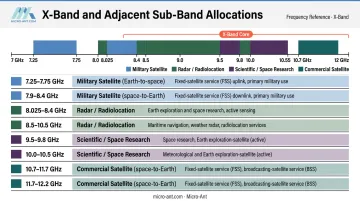
Two points that directly affect procurement decisions:
- Military SATCOM allocations (7.25–7.75 GHz downlink, 7.9–8.4 GHz uplink) sit below and adjacent to the IEEE radar X-band definition, not inside it. These are separate ITU service allocations, restricted to military users under national and NATO designations.
- NJFA requirements govern how NATO military X-band terminals operate within civil-military spectrum sharing arrangements. Equipment certification, regulatory compliance, and interoperability for defense customers follow NJFA agreements — not ITU civilian allocations.
Specifying a terminal as "X-band" without identifying the applicable allocation — ITU civilian, national military, or NATO NJFA — introduces concrete gaps in licensing, interference assessment, and certification scope. The allocation category must be defined before any compliance or procurement process begins.
Key Technical Properties of X-Band
Atmospheric Propagation and Rain Attenuation
The atmosphere is largely transparent at X-band frequencies under dry conditions. Liquid water changes that. Using the ITU-R P.838-3 specific attenuation model, attenuation at 10 GHz (horizontal polarization) runs approximately 0.220 dB/km at 10 mm/h rainfall and 0.696 dB/km at 25 mm/h rainfall.
For context across the microwave bands:
| Band | Frequency | Attenuation at 10 mm/h | Attenuation at 25 mm/h |
|---|---|---|---|
| S-band | 3 GHz | 0.002 dB/km | 0.007 dB/km |
| C-band | 6 GHz | 0.027 dB/km | 0.118 dB/km |
| X-band | 10 GHz | 0.220 dB/km | 0.696 dB/km |
| Ku-band | 15 GHz | 0.595 dB/km | 1.666 dB/km |
| Ka-band | 30 GHz | 2.134 dB/km | 5.089 dB/km |
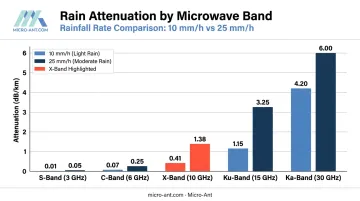
X-band is more rain-resilient than Ku and Ka, but not immune. At short radar ranges, this attenuation is manageable. At satellite link distances, a 0.220 dB/km loss accumulates across an oblique atmospheric path and must be designed into link margins using worst-case rain fade statistics for the deployment region. Omitting this from link budget analysis is one of the more common field deployment errors.
Spatial Resolution and Target Discrimination
Radar angular resolution scales approximately with λ/D — shorter wavelength over a given aperture diameter produces a narrower beam and finer target discrimination. At X-band wavelengths, a smaller aperture achieves the same beamwidth as a larger C- or S-band aperture, which is why X-band is the preferred choice for maritime surface tracking, imaging radar, and target identification.
Range resolution is governed by pulse bandwidth or pulse width, not carrier frequency alone. The correct claim for X-band is improved angular discrimination and compact-aperture gain — not automatic improvement in range resolution.
WMO-sourced material identifies X-band weather radars (9300–9500 MHz) as short-range instruments, useful up to roughly 50 km, while S-band systems cover longer-range weather surveillance. The same property that enables fine discrimination limits maximum effective range under adverse conditions.
Antenna Dimensions and System Compactness
Antenna gain and aperture are related by G = 4πA_e/λ². For a fixed gain target, the required aperture area falls with the square of the wavelength. X-band's ~3 cm wavelength allows antenna apertures considerably smaller than C- or S-band equivalents achieving comparable gain — a direct enabler of compact, lightweight designs for shipborne, airborne, and man-portable platforms.
This relationship has a practical boundary: antenna tuning, feed network impedance matching, and component performance are optimized for specific frequencies within the band. Operating significantly above or below the design center frequency increases side lobes, degrades gain, and raises VSWR. Engineers specifying wideband X-band systems need to verify that performance targets hold across the intended operating sub-band, not just at the design center.
Validating that performance across the sub-band requires test infrastructure that covers the full operating range. Micro-Ant's spherical and planar near-field test chambers span 750 MHz to 40 GHz, covering the full X-band and both adjacent military SATCOM allocations. Their AS9100:2016 and ISO 9001:2015 certified facilities support shipborne, airborne, and defense antenna programs requiring verified sub-band performance data.
X-Band Applications Across Defense, Maritime, and Space
Defense and Military Satellite Communications
Military X-band SATCOM operates on the 7.25–7.75 GHz downlink and 7.9–8.4 GHz uplink allocations — adjacent to, but separate from, the IEEE radar X-band definition. The U.S. Space Force's Wideband Global SATCOM (WGS) constellation provides X-band and Ka-band services to military users, with dedicated military X-band payloads as part of the modernized SATCOM architecture.
X-band is preferred for military SATCOM over commercial Ku and Ka for three concrete reasons:
- Weather resilience — substantially lower rain attenuation than Ku or Ka, improving link availability in contested or austere environments
- Terminal compactness — shorter wavelengths enable smaller, deployable antenna apertures meeting manpack and flyaway form factors
- Government-exclusive spectrum — military X-band allocations are restricted to government/military users, reducing civilian interference and improving covertness
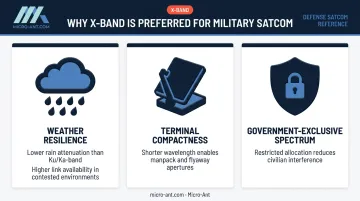
The UK's Skynet constellation and the U.S. WGS system both operate in military X-band. Terminal compactness requirements — particularly for manpack and flyaway configurations — drive demand for precisely engineered antenna apertures. Micro-Ant designs X-band antennas for these defense applications from its AS9100:2016 certified facility, with products qualified to MIL-STD-810 environmental standards and accepted under ARSTRAT certification requirements.
Radar: Maritime, Weather, and Surface Movement
X-band dominates maritime navigation radar. IMO MSC.192(79) requires X-band ship radar systems to detect SARTs (Search and Rescue Transponders), with SART use explicitly supported in the 9.2–9.5 GHz sub-band under ITU RR footnote 5.474. The higher angular resolution compared to S-band makes X-band the standard for obstacle detection and vessel tracking at close to medium range.
For weather radar, the picture is more nuanced:
- X-band weather radars (9300–9500 MHz) provide fine-scale, short-range precipitation observation — useful up to approximately 50 km
- S-band weather systems cover extended-range surveillance where X-band rain attenuation becomes limiting
- Attenuation correction algorithms extend X-band quantitative precipitation estimation range, though at the cost of added processing complexity
For air traffic control: the FAA's primary airport surveillance radar (ASR-11) operates in S-band at 2700–2900 MHz, not X-band. X-band does appear in airport surface movement radar — Singapore's A-SMGCS system, for example, uses three X-band surface movement radars for ground surveillance.
Deep Space and Scientific Communications
ITU RR footnote 5.465 reserves 8.4–8.45 GHz exclusively for deep space telecommunications. NASA's Deep Space Network uses X-band for spacecraft communication, with Voyager's high-gain antenna downlinking at approximately 8.4 GHz and the Mars Science Laboratory (Curiosity) using X-band as its primary downlink frequency.
The Viking relativity experiment demonstrated X-band's precision measurement utility: Viking orbiters transmitted coherent S-band and X-band signals (~8.4 GHz), enabling dual-frequency measurements to quantify solar-system radio propagation effects and verify General Relativity predictions. That level of relativistic measurement accuracy depended on X-band's stable, well-characterized propagation behavior — a property that continues to make it the default downlink frequency for deep space science missions.
How X-Band Is Specified, Measured, and Validated
Specification and Standards
X-band systems are specified against three distinct standards frameworks, and confusing them leads to compliance gaps:
- IEEE Std 521-2019 — defines X-band as 8.0–12.0 GHz for radar applications; the standard most antenna manufacturers and defense procurement documents cite
- ITU Radio Regulations — governs specific sub-band allocations for civil spectrum use; compliance means operating within the licensed allocation, not merely within the broad 8–12 GHz range
- NATO NJFA — governs military X-band SATCOM terminals operating in the 7.25–7.75 GHz / 7.9–8.4 GHz allocations under harmonized civil-military agreements
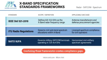
Regulatory compliance and performance specification are different things. Compliance means the operating frequency falls within the licensed allocation. Performance specification means antenna gain, beamwidth, and VSWR hit contractual targets at the design center frequency — and the test report must demonstrate this distinction clearly.
Measurement and Verification
Standard X-band antenna characterization uses:
- Near-field spherical and planar scanning chambers — most commonly used for production and qualification testing
- Far-field ranges — used where chamber size constraints apply
- Compact antenna test ranges — used for high-frequency systems requiring large aperture simulation
Micro-Ant operates spherical and planar near-field testing chambers covering 750 MHz to 40 GHz, fully encompassing X-band and adjacent military SATCOM allocations. Hardware never leaves the facility, which cuts lead time and preserves chain-of-custody for defense programs.
Testing follows AS9100:2016 certified processes, producing fully submittable characterization reports accepted by DoD procurement offices and satellite operators.
Key metrics verified during X-band antenna testing:
- Gain and gain-versus-frequency
- Beamwidth and beam shape
- Side-lobe levels
- Cross-polarization isolation
- VSWR across the operating sub-band
- Noise figure (where applicable)
One reality to plan for: chamber results and field measurements will diverge. Multipath from the platform structure, radome effects, environmental noise, and installation geometry all shift performance from the idealized chamber condition. Link margin design must account for this gap with explicit dB allocation — not absorbed into a general margin assumption.
Common Misinterpretations of X-Band in Practice
Two misconceptions consistently create field problems:
Treating the 8–12 GHz range as a single uniform band. Each sub-band carries distinct regulatory obligations, interference environments, and propagation conditions. A system specified as "X-band capable" can still be unlicensed, mismatched to available spectrum, or non-interoperable with the destination network — if the applicable sub-band allocation isn't named in the specification, the designation is incomplete.
Assuming X-band is weatherproof. X-band is substantially more rain-resilient than Ku or Ka, but rain fade budgeting is still required at satellite link distances. A link budget that ignores rain attenuation will show adequate margin on paper, then fail availability targets in high-rainfall regions. This failure is most common when systems move from temperate deployments to tropical environments without a revised link budget.
Frequently Asked Questions
What is the frequency range of the X-band?
Per IEEE Std 521-2019, X-band covers 8.0–12.0 GHz with corresponding free-space wavelengths of 3.75 cm (at 8 GHz) to 2.5 cm (at 12 GHz). The band falls within the ITU's Super High Frequency (SHF) classification, which spans 3–30 GHz.
What is the X-band frequency used for?
X-band supports a broad range of applications across its allocated sub-bands:
- Military and government SATCOM (7.25–7.75 GHz / 7.9–8.4 GHz allocations)
- Maritime navigation and short-range weather radar
- Airport surface movement radar
- Deep space telecommunications
- Terrestrial radiolocation
What does the "X" in X-band stand for?
The "X" comes from World War II-era radar classification systems designed to conceal operating frequencies from adversaries. No standards body ever assigned the letter a formal technical meaning. Post-war labels like "extreme" or "cross" are folk etymologies, not definitions recognized by any primary standard.
How does X-band compare to Ku-band and Ka-band?
X-band (8–12 GHz) provides greater weather resilience and longer effective satellite link availability than Ku (12–18 GHz) or Ka (26–40 GHz). The trade-off is lower maximum data throughput per unit bandwidth and the need for larger antenna apertures to achieve equivalent gain.
What are the main limitations of X-band for radar and satellite applications?
Key limitations include:
- Rain attenuation increases with path length, requiring explicit link margin budgeting for satellite links
- Shorter wavelengths that sharpen angular resolution also constrain effective radar range in adverse weather
- Adjacent sub-band interference in congested environments demands careful frequency coordination