That's a mistake. A 2026 U.S. Army Center for Army Lessons Learned report confirms HF radio can help joint forces maintain BLOS communications when satellite access is denied. The antenna feeding that radio determines whether the link actually works.
This guide covers HF fundamentals, the four major antenna configuration types used on military aircraft, design considerations for defense-grade systems, common installation pitfalls, and what to look for in a manufacturing partner.
Key Takeaways
- HF (3-30 MHz) uses ionospheric skywave propagation for BLOS communications without satellite dependence
- Four configuration families dominate airborne HF: wire/V, short grounded wire, shunt, and probe
- Aircraft type/speed and coupler location are the two variables that determine which configuration fits
- MIL-STD-810H and MIL-STD-461H govern environmental and EMI qualification, but tailoring matters more than a "MIL-STD certified" label
- Partner selection should weigh certifications, in-house testing, and engineering depth over a product catalog
What Is HF and Why It Matters in Defense & Aerospace Communications
HF refers to the 3-30 MHz frequency band, as defined by the ITU. What makes it valuable for military aviation isn't the frequency range itself, but how those signals travel.
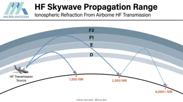
HF waves refract off the ionosphere's D, E, F1, and F2 layers and bend back toward Earth. This lets a signal skip over the horizon instead of traveling in a straight line like VHF or UHF.
According to FAA HF frequency management guidance, a single hop can theoretically cover 1,300 nautical miles via the E layer or 2,500 nautical miles via the F layer. Multiple hops can push that range past 8,000 nautical miles.
That reach is why defense programs keep investing in HF, even as SATCOM capability expands. Satellite links depend on infrastructure that adversaries can target: ground stations, uplinks, and the satellites themselves.
HF doesn't need any of that. It functions as a resilient fallback, keeping communications alive when space-based assets are contested or denied.
What an HF Antenna Actually Is
An HF antenna on an aircraft is a radiating element, usually a length of wire, a probe, or a shunt structure, connected to an antenna coupler. The coupler tunes the antenna's impedance across the HF band so the transmitter can push power efficiently at whatever frequency the mission requires.
Two variables drive which configuration works on a given airframe:
- Aircraft type and speed - drag tolerance and airframe geometry limit what's physically viable
- Antenna coupler location - forward-mounted couplers typically pair with long wire runs, while aft-mounted couplers suit shunt or inverted V setups
Get either variable wrong early in the program, and you're stuck retrofitting later.
Types of HF Aircraft Antennas
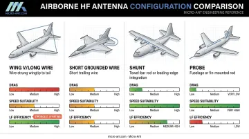
Airborne HF antennas generally fall into four configuration families. Each one trades electrical efficiency against drag, weight, and airframe integration differently, so the "best" choice always depends on the platform.
"V" and Long Wire Configurations
The wing "V" antenna produces an omnidirectional radiation pattern and works well on slower, moderate-speed aircraft. The tradeoff is drag. A wire antenna strung between wingtip and tail creates enough resistance that it's simply not viable on high-speed fixed-wing jets or helicopters.
Inverted V and long wire variants shift signal strength characteristics depending on geometry:
- Long wire configurations emphasize radiation off the sides rather than a true omnidirectional pattern
- Coupler placement (forward vs. aft) changes where nulls appear, typically off the nose or tail
- Low-frequency efficiency peaks with these configurations, exceeding every other HF antenna option
Short Grounded Wire Configuration
Higher-speed and high-altitude aircraft need something with less drag. A short grounded wire fits that requirement, but it comes at a cost.
Efficiency drops at the lower end of the HF band because a shorter electrical length can't couple as effectively to longer wavelengths. It also develops lower RF voltage than a long wire, per SEA Aerospace's airborne HF guidance. For jets that can't tolerate a trailing wire or wing-to-tail run, it's often the only practical option. Fighter aircraft and business jets commonly accept this tradeoff, since airframe speed and structural limits rule out longer wire runs entirely.
Shunt Configuration
Shunt antennas come in two distinct forms:
- Towel-bar shunt antennas - a rod or tube shunted to the airframe, common on helicopters where a low-profile, low-drag solution is essential
- Leading-edge shunt antennas - integrated directly into the vertical stabilizer structure, typically found on larger, high-altitude jets like C-130 and 737-class airframes
Both eliminate the drag penalty of a trailing wire, but they require careful structural integration since the antenna becomes part of the airframe itself.
Probe Configuration
Probe antennas offer a low-profile option when longer wire runs simply aren't feasible on the platform. Like other electrically short configurations, they lose efficiency at lower HF frequencies. They're best suited to aircraft where installation constraints outweigh the need for maximum low-band performance. Fast movers and some rotorcraft mount probe antennas on the fuselage or fin cap, trading low-band range for a rugged, aerodynamically clean installation that survives high-speed flight.
Design & Performance Considerations for Military-Grade HF Antennas
Choosing a configuration is step one. Getting the design right for defense-grade reliability requires working through several additional layers.
Frequency bandwidth and tuning range. Multi-mission platforms need antennas that support interoperability across different HF sub-bands without manual reconfiguration. A narrow tuning range limits mission flexibility.
Power handling and RF voltage tolerance. Long-range military HF transmission demands high-power handling. Product benchmarks illustrate the range: Collins' HF-9500 system is rated at 400 W, while Dayton-Granger's towel-bar antenna handles 200 W continuous wave / 400 W peak envelope power. These are platform-specific figures, not a universal spec, so power requirements should be defined per program.
Aerodynamic drag vs. structural integration. Speed and altitude dictate configuration:
| Aircraft Profile | Typical Configuration |
|---|---|
| Slow/moderate-speed fixed-wing | Wing V, long wire |
| High-speed jets | Short grounded wire, probe |
| Helicopters | Towel-bar shunt |
| Large, high-altitude jets | Leading-edge shunt |
Environmental ruggedization. As of 2026, the active standards are MIL-STD-810H Change 1 (environmental) and MIL-STD-461H (EMI/EMC), not the older 461G revision some legacy documentation still references. These standards require testing to specific tailored methods, meaning:
- Temperature extremes (high and low)
- Vibration profiles matched to platform and mission
- Humidity exposure
- Altitude/low-pressure testing
A blanket "MIL-STD certified" claim doesn't mean much. Ask which revision and which test methods were applied. Because Micro-Ant designs, builds, and tests antennas in-house at its Jacksonville, Florida facility, MIL-STD-810H and MIL-STD-461H validation happens under one roof, avoiding the schedule risk of shipping hardware to third-party labs for environmental and EMI/EMC testing.
Electrical bonding and grounding. FAA guidance specifies direct metal-to-metal contact at the antenna base, with a maximum bond resistance of 0.003 ohm. Moisture at that bond point is a leading cause of corrosion and performance loss.
EMI/EMC considerations. Antenna placement matters as much as antenna design. FAA advisory material suggests keeping antennas as far as practicable from other radiating sources, with 36 inches offered as a general rule of thumb, not a fixed military requirement. Co-located GPS, transponder, and SATCOM antennas all need dedicated EMC analysis during placement planning.
Common Installation Challenges and Best Practices
Even a well-designed HF antenna can underperform if installation decisions come too late or maintenance gets overlooked.
Coupler location drives everything. Deciding on forward vs. aft coupler placement early in program design determines which of the four configurations is even viable. Retrofitting a different configuration after airframe finalization is expensive and sometimes impossible.
Maintenance pitfalls to watch:
- Corrosion at the bond point - FAA guidance prohibits it
- Poor contact points - dirty or degraded bonding surfaces distort radiation patterns and create coverage nulls
These maintenance issues are far cheaper to prevent than to fix once an aircraft is fielded. Pre-installation testing matters. Confirming VSWR performance and radiation pattern behavior before an antenna goes operational catches problems while they're still cheap to fix. Waiting until an aircraft is fielded to discover a coverage null off the tail is a costly way to learn that lesson.
Choosing the Right HF Antenna Manufacturing Partner for Defense & Aerospace Programs
HF antenna programs for military and government aircraft carry requirements that go beyond RF performance. The manufacturing partner matters as much as the design.
What separates a qualified manufacturing partner from a merely capable one comes down to four factors:
- Certifications and traceability. AS9100:2016 and ISO 9001:2015 establish the quality management systems defense contracting officers expect. Micro-Ant holds both, backed by an ERP-based system that traces every unit from raw materials through final characterization.
- In-house testing. Micro-Ant's Jacksonville facility runs spherical and planar near-field chambers covering 750 MHz to 40 GHz, validating antenna performance domestically instead of relying on overseas labs.
- Custom engineering depth. Over 20 years designing bespoke GNSS, SATCOM, and electronic warfare antennas for DoD, civil government, and aerospace primes — the depth needed when an off-the-shelf configuration doesn't fit an unusual airframe.
- Supply chain compliance. CAGE code 6XJFO and Made-in-the-USA manufacturing from Micro-Ant's Jacksonville headquarters support defense procurement requirements for domestic sourcing and traceability.

If your program needs a custom HF antenna configuration engineered around a specific airframe and mission profile, that's a conversation worth having early, before coupler location and airframe geometry get locked in.
Frequently Asked Questions
What is HF in aircraft communications?
HF refers to the 3-30 MHz frequency band used for long-range, beyond-line-of-sight communication through ionospheric skywave propagation. This is common in military aviation and remote operations where satellite links are not reliable.
What is an HF antenna on an aircraft?
This is a radiating element, typically wire, probe, or shunt-based, connected to an HF coupler. The coupler tunes the antenna across the HF band so it matches the aircraft's impedance for transmission and reception.
What are the three basic types of antennas used on aircraft?
Broadly, aircraft antennas fall into wire/long-wire, blade/rod, and flush or conformal mounted types. The four HF-specific configurations covered earlier fall within the wire/long-wire category, representing a more detailed breakdown of that broader type.
How does an HF antenna differ from VHF or UHF antennas on an aircraft?
HF relies on ionospheric skywave propagation for long-range, beyond-line-of-sight range and typically requires a larger radiating element. VHF and UHF antennas use line-of-sight propagation for shorter-range communications, navigation, and transponder functions.
What certifications should a defense antenna manufacturer hold?
AS9100 and ISO 9001 are baseline quality management standards for defense and aerospace suppliers. A CAGE code and US-based manufacturing add further supply chain compliance value for government procurement.
How does antenna coupler location affect HF antenna selection?
Forward-mounted couplers typically pair with long wire antenna runs, while aft-mounted couplers suit inverted V or shunt configurations. This decision needs to happen early in program design since it limits which configurations are viable later.