Introduction
5G rollouts, satellite mega-constellations, and defense platforms are converging onto the same hardware. A single terminal now needs to talk to multiple networks and operators across shifting frequency plans without a rack of separate antennas bolted to the chassis.
This creates a real problem for traditional microstrip patch antennas. Conventional patches are narrowband by nature, often locked to just a few percent of bandwidth around one center frequency. Engineers historically solved this by stacking multiple antennas onto a platform, adding weight and cost that aircraft, vessels, and vehicles can't always spare.
Wideband microstrip patch antennas solve that bottleneck. This article explains what makes a patch "wideband," the structural tricks engineers use to widen it, and where these designs show up in real satcom, 5G, and defense systems.
Key Takeaways
- Standard patch antennas deliver only 2-5% fractional bandwidth; wideband designs can exceed 40-70%
- Slots, defected ground structures, parasitic elements, and specialized feeds are the primary bandwidth-widening tools
- Wideband patches enable multiband, multi-operator connectivity across satcom, 5G sub-6 GHz, and GNSS
- Bandwidth gains trade off against gain stability, size, and fabrication precision
- Micro-Ant engineers and tests bespoke wideband systems, including its Ultra-Wide Band Ka Antenna System
What Is a Microstrip Patch Antenna?
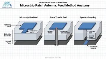
A microstrip patch antenna is about as simple as antennas get, at least structurally. It's a flat conductive patch sitting on top of a dielectric substrate, with a ground plane underneath. Engineers feed it one of three common ways:
- Microstrip line feed - a printed trace connects directly to the patch edge
- Probe or coaxial feed - a connector passes through the ground plane into the patch
- Aperture coupling - a slot in the ground plane couples energy from a feed line below
Why Engineers Love the Patch Form Factor
The patch resonates at a frequency set almost entirely by its physical dimensions (length and width) and the substrate's dielectric constant. Change the length, and the resonant frequency shifts. A patch designed for 2.4 GHz Wi-Fi, for example, typically measures around 30mm by 40mm on standard FR4 substrate.
That predictability, combined with a flat, low-profile footprint, is exactly why patches dominate PCB-mounted and vehicle-surface antenna designs. They're lightweight, cheap to fabricate, and easy to integrate into aircraft skins, drone bodies, or ground vehicle roofs.
The Narrowband Catch
Here's the trade-off: a basic rectangular or circular patch is a high-Q resonant structure. High Q means the antenna stores energy efficiently at one frequency but radiates well only over a narrow slice around it, commonly just 2-5% fractional bandwidth. Push outside that window and return loss degrades fast.
Bandwidth isn't the only constraint, either. Standard patches typically transmit or receive in just a single, fixed polarization. For systems that need to switch between signal types or operators, that's a real limitation. This narrowband, single-polarization nature is precisely the problem that wideband patch engineering exists to fix.
What Makes a Patch Antenna "Wideband"?
Bandwidth isn't a vague marketing term here. Engineers define impedance bandwidth as the continuous frequency range where the antenna holds an acceptable return loss, commonly |S11| ≤ -10 dB or VSWR ≤ 2. Outside that range, too much signal reflects back instead of radiating.
To compare antennas of different sizes and center frequencies fairly, engineers use fractional bandwidth (FBW):
FBW = (Upper frequency − Lower frequency) ÷ Center frequency × 100%
Where the Thresholds Actually Sit
There's no single industry-wide cutoff for "wideband." The FCC's own definition of ultra-wideband, at least 20% fractional bandwidth or 500 MHz of bandwidth, is a regulatory rule for Part 15 devices, not a universal antenna classification.
Most working engineers still treat roughly 20% and up as a reasonable practical threshold for "wideband," with advanced designs pushing past 40-70%.
Published research backs this up. A dual-polarized hexagonal patch antenna design using a coax feed and three-slit geometry achieved a simulated 42.4% fractional bandwidth from 2.4 to 3.69 GHz, with gain climbing from 3.7 dBi to 5.9 dBi across the band. That's real proof that clever geometry, not just brute-force size, drives bandwidth.
The physics underneath all of this comes down to Q. Widening bandwidth means lowering the antenna's quality factor, which increases radiated energy but risks degrading gain flatness or efficiency if it's not managed carefully.
Design Techniques Engineers Use to Achieve Wideband Performance
No single trick gets a patch from 3% to 40% bandwidth. Engineers layer several techniques together, each adding or merging resonances until the individual bands blend into one continuous operating range.
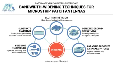
Slotting the radiating patch. Cutting slots (I-shaped, L-shaped, U-shaped) into the patch surface lengthens the current path the signal travels. That extra path length introduces additional resonant modes near the primary frequency, and when tuned correctly, those modes merge to widen the band.
Defected ground structures (DGS). Etching patterns into the ground plane, rather than the patch itself, disrupts current flow underneath. This creates capacitive loading that fine-tunes impedance matching and suppresses unwanted higher-order modes.
One published 5.8 GHz design using a thumb-shaped DGS pushed measured bandwidth from 180 MHz to 580 MHz, though gain dropped to 4.4 dBi as a trade-off.
Parasitic elements and stacked patches. Adding a secondary radiating element, whether a parasitic stub beside the main patch or a second patch stacked above it, creates multiple closely spaced resonances. Combined, they behave like one wide operating band instead of two narrow ones.
Feed line techniques. Three approaches dominate here:
- Aperture coupling for isolation between feed and radiating layers
- Proximity coupling for broader impedance matching
- Meandered feed lines, which elongate the electrical current path to shift resonance lower without growing the antenna's physical footprint
Substrate selection. Thicker substrates with lower dielectric constants generally support wider bandwidths. The catch: thicker, lower-Dk substrates also increase antenna size and surface wave losses, so this becomes a genuine size-versus-bandwidth negotiation.
Combining these techniques compounds the gains. One recent sub-6 GHz design merged circular parasitic stubs, L-slots, a meandered feed, and DGS into a single 36 x 20 x 1.6 mm patch, achieving a measured 3.2-6.6 GHz range, roughly 69.4% fractional bandwidth, in one compact footprint.
That's the kind of layered engineering Micro-Ant applies when a customer needs one antenna to cover territory that used to require two or three.
Where Wideband Microstrip Patch Antennas Are Used
Wideband patches show up wherever a platform can't afford to carry a separate antenna for every band.
Satellite communications. Wideband Ka-band designs let terminals roam across multiple satellite operators and frequency plans without swapping hardware mid-mission. Micro-Ant's Ultra-Wide Band (3.5 GHz) Ka Antenna System was built around exactly this capability, extending connectivity across Ka-band operator plans in a single unit. The system won the 2022 SatCom Technology of the Year Award in the Most Innovative category.
5G and wireless infrastructure. Sub-6 GHz wideband patches let a single compact device cover multiple carrier bands, useful for telecom base stations and IoT deployments where physical space is limited and hardware count directly drives cost.
Defense, aviation, maritime, and GNSS. These sectors demand ruggedized, multiband antennas that keep working through vibration, temperature swings, and salt exposure while supporting:
- Navigation and positioning across multiple constellations
- Tactical communications across shifting frequency plans
- Tracking and surveillance on moving platforms, from aircraft to unmanned vehicles
Advantages, Trade-offs, and Why Custom Engineering Matters
The case for wideband patches on any multiband platform is straightforward. Fewer antennas per platform means less weight, less drag, and less real estate consumed on an aircraft skin or ship mast. One wideband unit replacing three narrowband ones also simplifies integration, cabling, and maintenance.
But wideband performance doesn't come free. Common trade-offs include:
- Gain fluctuation across the operating band, since a design optimized for wide impedance matching doesn't always hold flat gain everywhere in that range
- Increased design complexity, since slots, DGS, and parasitic elements all interact and require careful co-simulation
- Greater fabrication sensitivity, where small variations in dielectric constant, etching precision, or connector soldering can shift measured performance noticeably from simulation
That last point is why simulation alone can't validate a wideband design. Published fabrication studies have documented real-world S11 shifts of 15-20 dB between simulated and measured results on patch prototypes, driven by dimensional errors as small as 0.2-0.3 mm. On a wideband patch, where multiple resonances have to merge precisely, that kind of tolerance drift becomes especially critical.
This is where physical testing earns its keep. Micro-Ant runs bespoke wideband designs through spherical and planar near-field testing chambers covering 750 MHz to 40 GHz at its Jacksonville, Florida facility, catching gain or impedance deviations before a design ships. Work on these designs is led by Chief Scientist Charles McCarrick, who brings over two decades of antenna engineering experience to every program. He treats the simulation-to-measurement gap as a core design step, cutting down costly redesign cycles for custom builds.

Frequently Asked Questions
What is the difference between a microstrip patch antenna and a wideband patch antenna?
A standard patch resonates narrowly around one frequency, typically just a few percent of bandwidth. Engineers add slots, defected ground structures, or parasitic elements to wideband versions, letting them operate reliably across a much broader frequency range.
How wide does an antenna's bandwidth need to be to be considered "wideband"?
No single universal cutoff exists, but many engineers treat fractional bandwidths above roughly 20% as wideband, with some advanced designs exceeding 40-70%.
What is the typical bandwidth of a standard microstrip patch antenna?
Conventional rectangular or circular patches typically achieve only about 2-5% fractional bandwidth due to their high-Q resonant structure.
Can a wideband microstrip patch antenna support multiple frequency bands at once?
Yes. Wideband and multiband designs can cover several application bands, or even dual polarizations, within a single radiating structure.
What substrate materials or thicknesses are best for wideband patch antenna design?
Thicker substrates with lower dielectric constants generally widen bandwidth but increase antenna size and surface wave losses, requiring careful trade-off analysis.
Which industries rely most on wideband microstrip patch antennas?
Satellite communications, 5G and telecom, defense, aviation, maritime, and GNSS or autonomous vehicle applications are the primary users of this technology.