Introduction
Walk onto a military transport, a commercial widebody, or a mid-size business jet today, and you'll find a SATCOM antenna somewhere on the fuselage or tail. It's what keeps voice, data, and video links alive long after VHF and HF radio lose their grip.
Demand for these systems is climbing fast. The airborne SATCOM market sat at $5.18 billion in 2024 and is projected to reach $10.24 billion by 2035, growing at a 6.39% CAGR, according to Market Research Future. The antenna segment alone is expected to roughly double, from about $1.5 billion to $3 billion, per the same analysis.
Yet most operators and engineers only understand SATCOM antennas at a surface level. That gap leads to mismatched antenna types, band incompatibilities, and integration headaches down the line. This guide breaks down exactly how an aircraft SATCOM antenna works, stage by stage, not just the theory behind it.
Key Takeaways
- SATCOM antennas connect aircraft to satellites through four stages: acquisition, tracking, processing, and output
- Mechanically steered dishes, phased arrays, and electronically steered arrays (ESAs) each track satellites differently
- GEO and LEO systems solve different problems; data rates span under 1 Mbps to over 190 Mbps
- Band choice (L, Ku, or Ka) determines antenna size, bandwidth, and which networks the aircraft can reach
What Is an Aircraft SATCOM Antenna?
An aircraft SATCOM antenna is a transmit/receive system mounted on the fuselage, tail, or fin that exchanges RF signals with geostationary or non-geostationary satellites to support voice, data, and connectivity services. It's the physical link between the aircraft and the satellite network, and every other onboard communication system depends on it.
Why it exists: VHF and HF radio depend on line-of-sight or ionospheric propagation, both of which weaken over oceans, poles, and remote continental airspace. FAA guidance identifies HF and satellite voice as the preferred long-range capabilities in oceanic airspace, precisely because VHF coverage is fundamentally limited by line of sight. SATCOM fills that gap.
What It Isn't
Don't confuse a SATCOM antenna with these related but distinct systems:
- GNSS/GPS antennas: receive-only, used purely for positioning
- VHF/HF radio antennas: line-of-sight or ionospheric, not satellite-based
- SATCOM antennas: two-way, built specifically for beyond-line-of-sight comms
Why It Still Matters as 5G Expands
Ground infrastructure keeps improving, but neither 5G towers nor terrestrial networks reach mid-ocean or polar airspace. Military and commercial aircraft still depend on satellite links for secure, continuous coverage where nothing else works.
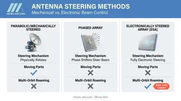
Antenna type also shapes how the system operates. Parabolic/mechanically steered antennas physically rotate to track a satellite, while phased array and electronically steered antennas (ESA) use electronic beam steering with no moving parts.
Micro-Ant's Ultra-Wide Band Ka Antenna System is one example of this shift, built for roaming across multiple satellite operators and orbits rather than locking to a single network.
How Does an Aircraft SATCOM Antenna Work?
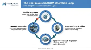
At its simplest, the antenna runs a continuous loop: acquire the satellite, track it, process the signal, and hand data or voice to onboard systems. That loop never really stops during flight.
Satellite Acquisition (Initiation)
The antenna controller pulls position and heading data from the aircraft's GPS/INS systems to calculate an initial look angle toward the target satellite. This isn't a one-time calculation.
- It engages automatically at power-up
- It recalculates continuously as the aircraft changes position and heading
- It runs without pilot input under normal operation
Common bottleneck: Acquisition weakens at high latitudes. Geostationary satellites sit over the equator, so their apparent elevation drops toward the horizon as an aircraft moves poleward: terrain, airframe blockage, and eventually the curvature of the Earth itself cut off the signal. ICAO guidance notes that HFDL fills this gap, providing polar data-link coverage where GEO-based SATCOM simply has none.
Beam Steering & Tracking (Core Operation)
Once locked on, the antenna has to hold that lock while the aircraft rolls, pitches, yaws, and moves at several hundred knots. This is the part that actually keeps the connection alive.
Parabolic dishes use a gimbal to physically rotate and re-point at the satellite, while phased array antennas use phase shifters across multiple elements to steer the beam electronically, with no moving parts at all.
Pointing accuracy and tracking speed directly determine signal strength and achievable data rate. The difference between GEO and LEO/MEO systems here is significant:
| System | Typical Speed | Notes |
|---|---|---|
| GEO (Inmarsat GX Aviation) | Up to 50 Mbps | Advertised maximum for airliners/business jets |
| LEO (Iridium Certus 700) | 0.704 Mbps down / 0.352 Mbps up | L-band, prioritizes global coverage over speed |
| LEO broadband (2025 terminal) | Up to 195 Mbps | Sub-100ms latency, per Iridium's own launch data on newer aviation terminals |
Orbit alone doesn't dictate speed: band, terminal design, and service plan matter just as much.
Signal Processing & Regulation
Raw RF isn't usable on its own. Outgoing signals pass through a high-power amplifier before transmission; incoming signals get cleaned up by a low-noise amplifier before the satellite data unit decodes them.
Two things have to line up for any of this to work:
Polarization must match the satellite's transmit/receive polarity, and frequency must fall within the exact band each satellite operator requires for a valid link.
This stage matters because dynamic control loops constantly correct for aircraft maneuvers. Without them, connections drop during beam handoffs. LEO systems face this most often: satellites move fast enough that the terminal must repeatedly transfer service to a new spacecraft as the current one moves out of range, a process that happens multiple times during a single flight.
Output & Integration
The end result of all this is a continuous two-way data and/or voice link between the aircraft and the satellite network, delivered through the satellite data unit.
That output feeds two very different downstream paths:
Cockpit avionics rely on this link for ATC data link services like CPDLC (Controller-Pilot Data Link Communications), while cabin systems use it to power in-flight Wi-Fi and passenger connectivity.
Real-world performance varies just as widely as the table above suggests, which is exactly why matching antenna architecture to mission requirements matters more than chasing a single headline speed number.
Where Is Aircraft SATCOM Antenna Used?
SATCOM antennas split into two operational roles on most aircraft: cockpit-integrated systems handle oceanic and remote ATC data link communications, while cabin-integrated systems deliver passenger broadband and in-flight entertainment connectivity.
Both have to survive conditions that would kill consumer-grade hardware:
- High altitude and pressure differentials
- Temperature swings from ground heat to stratospheric cold
- Constant vibration from engines and airframe flex
- Mounting on curved fuselage sections with limited real estate
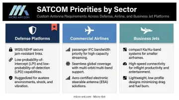
Requirements shift by sector, too:
- Defense platforms prioritize secure military satellite links, such as WGS for high-capacity communications and AEHF for protected, jam-resistant links
- Commercial airlines prioritize passenger IFC bandwidth above nearly everything else
- Business jets increasingly adopt compact Ka/Ku-band systems that fit smaller airframes without sacrificing throughput
Micro-Ant designs and tests bespoke antennas across defense, aviation, maritime, and land applications specifically because these operational demands don't overlap neatly — a fix for one platform rarely transfers cleanly to another.
Conclusion
An aircraft SATCOM antenna works as a continuous cycle: acquire the satellite, track it through every roll and pitch, process the signal cleanly, and hand a stable link to cockpit or cabin systems. Break any one stage, and the whole connection suffers.
Understanding that cycle changes how operators and engineers evaluate antenna type and band compatibility, weighing long-term vendor reliability alongside the spec sheet. Companies like Micro-Ant, with over 20 years of antenna design experience and in-house testing chambers in Jacksonville, Florida, support exactly this kind of informed selection process before an antenna ever reaches the tarmac.
Frequently Asked Questions
How does a SATCOM antenna work?
It runs a continuous cycle of satellite acquisition, beam tracking, signal processing, and output to onboard systems. Each stage depends on the previous one holding steady, especially during aircraft maneuvers.
What are the three basic types of antennas used in aviation?
Parabolic/mechanically steered antennas physically rotate on a gimbal. Phased array antennas use phase shifters to steer electronically. Electronically steered arrays (ESAs) take this further, with no moving parts at all.
What is the difference between GEO and LEO satellite antennas?
GEO antennas track a satellite that appears nearly fixed in the sky, simplifying pointing. LEO antennas must rapidly switch between fast-moving satellites, adding handoff complexity but often reducing latency.
Why do aircraft need SATCOM antennas?
VHF and HF radio lose reliability over oceans, poles, and remote continental airspace due to line-of-sight and propagation limits. SATCOM fills that coverage gap with a continuous satellite link.
How is a SATCOM antenna tested before installation on an aircraft?
Testing typically covers lab-level component checks, environmental and vibration testing, and flight trials before certification. In-house testing chambers, like Micro-Ant's spherical and planar near-field setups covering 750 MHz to 40 GHz, shorten this timeline by keeping every stage under one roof.
What frequency bands do aircraft SATCOM antennas use?
L-band favors coverage and resilient voice/data at modest speeds. Ku-band adds more bandwidth for cabin broadband. Ka-band supports the highest throughput but demands tighter pointing accuracy and band matching.