Introduction
Every connected device on the planet relies on one component to talk to the outside world: the antenna. Smartphones, radar systems, satellites, and shipborne SATCOM terminals all depend on a well-engineered RF antenna to move signals between guided electronics and free space.
That engineering job is harder than it looks. Designers juggle frequency, physical size, material properties, and environmental durability all at once. Get one wrong, and the whole wireless or SATCOM link suffers — dropped connections, reduced range, or outright failure in the field.
This guide breaks down how RF antennas work, the main design types, the critical decisions engineers face, material tradeoffs, and why testing and manufacturing partnerships matter for mission-critical programs.
Key Takeaways
- RF antennas convert electrical signals into electromagnetic waves, with performance shaped by gain, directivity, bandwidth, and polarization
- Four core antenna types exist: wire, aperture, microstrip/patch, and array, each suited to different platforms and missions
- Frequency, environment, and material choice determine range, durability, and long-term reliability
- Simulation plus physical anechoic chamber testing catches problems before they become field failures
- Harsh-environment applications like defense and SATCOM often require bespoke designs that off-the-shelf antennas can't match
How Does an RF Antenna Work? Understanding the Fundamentals
An antenna is a two-way translator. On transmit, it converts voltage and current from a feedline into radiated electromagnetic waves. On receive, it reverses the process, converting incoming waves back into a voltage signal. This property, known as reciprocity, means the same antenna can typically serve both roles equally well.
The radiation itself comes from accelerating electric charges along the antenna's conductive elements. Close to the antenna, in the near-field region, the electromagnetic fields are complex and don't behave predictably.
Move beyond a distance defined roughly by the Fraunhofer boundary (R = 2D²/λ, where D is the antenna's largest dimension), and you enter the far-field region. This is the zone that actually carries usable signal over distance.
The Four Metrics Every Engineer Tracks
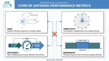
IEEE defines a specific set of performance parameters that govern antenna behavior:
- Gain: radiation intensity in a given direction compared to an ideal isotropic radiator
- Directivity: how concentrated the radiated energy is in one direction versus spread evenly
- Efficiency: the ratio of radiated power to power actually delivered to the antenna
- Bandwidth: the frequency range where a specified performance criterion (impedance, gain, or axial ratio) is met
Gain matters more than most engineers initially assume. Under standard free-space link-budget assumptions, a 3 dB gain increase adds roughly 3 dB of received power, roughly doubling signal strength with everything else held constant, according to ITU link-budget training materials.
That modest-sounding gain bump can translate into meaningfully extended range or lower transmit power requirements, which matters for battery-powered or power-constrained platforms.
Polarization and Impedance Matching
Polarization, whether linear or circular, describes the orientation of the radiated wave. Mismatched polarization between a transmitting and receiving antenna causes real signal loss, sometimes severe enough to break a link entirely.
Impedance matching is equally critical. Most antennas are matched to a 50-ohm feedline, the standard resistive reference used across RF systems. Poor matching reflects power back toward the source instead of radiating it, a problem engineers quantify using VSWR and return loss. The Smith Chart remains the go-to tool for visualizing and correcting these mismatches during design.
What Are the Main Types of RF Antennas?
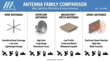
Antenna designs generally fall into four families, and each one fits a different mission profile.
Wire Antennas
Dipoles, monopoles, and Yagi-Uda arrays make up this category. They're simple, inexpensive, and broadly omnidirectional, ideal for broadcast, point-to-point links, and consumer wireless devices. A Yagi-Uda design adds parasitic directors and reflectors to a driven element, giving it directional gain useful for fixed links.
Aperture Antennas
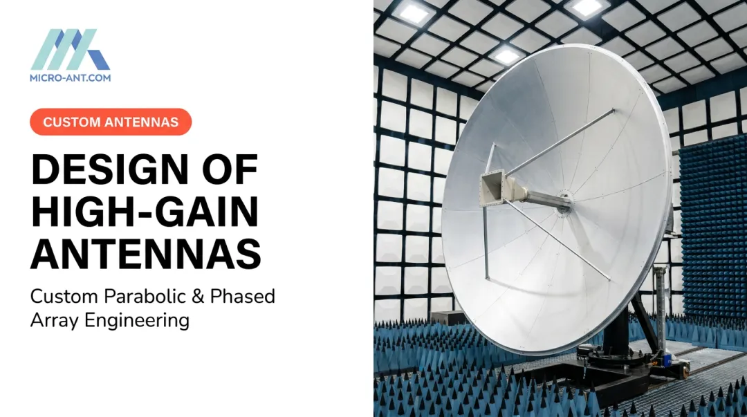
Horn and parabolic reflector antennas dominate this category. Their large radiating apertures deliver high gain over long distances, which is why radar systems and satellite links depend on them heavily. A horn antenna can operate alone or serve as the feed for a larger parabolic reflector.
Microstrip/Patch Antennas
These low-profile, PCB-integrated radiators show up everywhere space is tight: mobile devices, GPS/GNSS receivers, and compact wireless products. Their flat form factor makes them easy to integrate into vehicle bodies and aircraft skins without adding bulk.
Array Antennas and Phased Arrays
Multiple radiating elements working together enable beamforming, higher directivity, and (in phased arrays) electronic beam steering without moving parts. This capability is fueling rapid growth: the satellite phased-array market alone was valued at $1.9 billion in 2024 and is projected to grow at a 15.6% CAGR through 2034, according to Global Market Insights. Radar and 5G infrastructure lead that demand, with LEO/MEO SATCOM terminal deployments close behind.
Textbook classifications only get you so far. Multi-band SATCOM, maritime shipboard, and precision GNSS applications frequently demand hybrid or custom-engineered variants that blend characteristics across these four categories. Micro-Ant's flat panel antenna line, for example, spans more than 15 distinct configurations built to match specific platform and frequency requirements rather than forcing a customer into a fixed catalog design.
Key Considerations in RF Antenna Design
Every antenna project comes down to a set of interlocking tradeoffs. Get the balance wrong, and something else in the system pays the price.
Frequency and bandwidth. Higher operating frequency means shorter wavelength (λ = c/f), which generally means a smaller physical antenna. But multi-band or wideband requirements, common in SATCOM roaming across operators, add real complexity to matching and pattern performance.
Size and integration constraints. Aircraft, vessels, and vehicles rarely offer generous real estate for antennas. Techniques like meandering fold a longer electrical path into a smaller physical footprint. One published example demonstrated a miniaturized meander-line monopole operating at 140 MHz, showing how far this technique can be pushed when space is scarce.
Environmental durability. MIL-STD-810H defines separate, tailored test methods for the conditions antennas actually face:
| Method | Environmental Stress |
|---|---|
| 501.7 | High Temperature |
| 502.7 | Low Temperature |
| 507.6 | Humidity |
| 509.7 | Salt Fog |
| 514.8 | General Vibration |
| 528.1 | Shipboard Mechanical Vibration |
A generic "MIL-STD-810 tested" claim isn't enough: the specific method, severity, and platform profile all matter.
Regulatory compliance. FCC Part 2 authorization, RF exposure limits under 47 CFR 1.1310, and ETSI standards for SATCOM earth stations all shape what's legally deployable, depending on band and market.
Cost and manufacturability. Custom engineering costs more upfront than COTS antennas, but for low-volume, mission-critical programs, that investment often pays for itself in reliability.
Simulation methods. EM solvers each suit different geometries:
- Method of Moments (MoM) handles wire antennas efficiently
- Finite Element Method (FEM) manages complex 3D volumes and multiport structures
- Finite-Difference Time-Domain (FDTD) captures broadband transient behavior in a single simulation run
Choosing the Best Material for RF Antenna Performance
Material selection isn't cosmetic. It determines conductivity, weight, loss, and how long an antenna survives in the field.
Conductive Elements
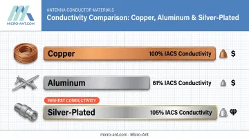
- Copper — the conductivity reference standard; heavier but highly efficient
- Aluminum — roughly 61% of copper's conductivity, but significantly lighter, a common tradeoff for airborne platforms
- Silver-plated conductors — the highest elemental conductivity available, often used selectively where every fraction of a dB matters
Substrate and Dielectric Materials
For patch antennas, the PCB laminate directly shapes performance, especially at higher frequencies. The gap between grades is not small:
| Laminate | Dielectric Constant | Loss Tangent (10 GHz) |
|---|---|---|
| Isola 370HR (FR-4) | 3.63 | 0.0300 |
| Rogers RO4003C | 3.38 ± 0.05 | 0.0027 |
That's roughly a tenfold difference in loss tangent between a standard FR-4 construction and a low-loss Rogers-type laminate, based on Isola's published Dk/Df data. At higher microwave frequencies, that difference shows up directly as reduced efficiency and gain.
Radome and Housing Materials
Fiberglass and PTFE composites protect antennas in maritime, aviation, and outdoor defense environments while staying low-permittivity and largely "transparent" to signal. Lower dielectric constant improves impedance match toward free space; lower loss tangent means less energy absorbed as the signal passes through.
For extreme field conditions, purpose-built composite systems go further. Micro-Ant's Kore Composites Veritas Tri-Band Segmented Reflector and Feed system, for instance, uses carbon fiber embedded in a specialized resin with no conductor in the reflector material itself.
This conductor-free construction avoids the thermal expansion and interference issues metallic reflectors introduce. It allows for tri-band operation while meeting the strict rigidity and surface standards demanded by manpack and flyaway terminal deployments.
Testing, Validation, and Choosing the Right Manufacturing Partner
Simulation catches problems early. Physical testing confirms them.
EM simulation validates impedance matching and radiation pattern predictions before a single prototype gets built, saving both time and fabrication cost. But simulation alone can't replace measured data.
Physical testing happens across two distinct domains:
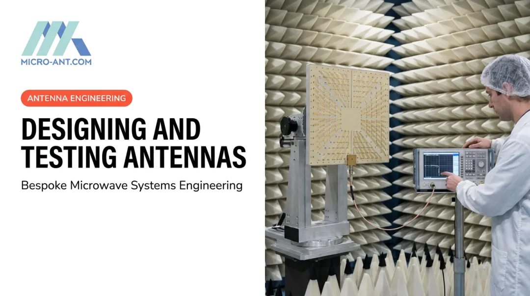
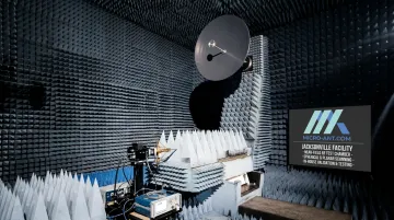
- Radiation testing in anechoic chambers, measuring gain, radiation pattern, and polarization in either far-field ranges or near-field setups (which then require mathematical transformation to far-field data)
- Port-level testing using a vector network analyzer to measure return loss, impedance, and VSWR
Both matter. A supplier who only shows one half of that picture isn't giving you the full one.
Micro-Ant runs its own spherical and planar near-field test chambers covering 750 MHz to 40 GHz at its Jacksonville, Florida facility. Keeping testing in-house and US-based cuts travel time and shipping delays for customers who need quick-turnaround validation instead of waiting on a third-party lab's schedule.
For mission-critical defense, SATCOM, and aerospace programs, working with an AS9100:2016 and ISO 9001:2015 certified manufacturer adds another layer of assurance. Certification alone doesn't prove RF performance, but paired with decades of in-house design, build, and test experience, it signals a partner equipped to catch problems generic COTS suppliers often miss.
That combination shows up when it matters most:
- Traceability runs from initial design through final delivery
- Test data holds up under government or prime contractor audit
Frequently Asked Questions
How does an RF antenna work?
An RF antenna converts electrical signals from a feedline into radiated electromagnetic waves for transmission. It also reverses that process, converting incoming waves back into a voltage signal for reception. This works both ways thanks to antenna reciprocity.
What is the best material for RF antenna?
Material choice depends on the application. Copper or aluminum works well for conductive elements, low-loss laminates like Rogers suit high-frequency patch antennas, and rugged composites such as fiberglass or carbon fiber handle harsh-environment housings and reflectors.
What are the 4 types of antennas?
The four primary classifications are wire (dipole, monopole, Yagi-Uda), aperture (horn, parabolic reflector), microstrip/patch, and array (including phased arrays). Each suits different range, gain, and integration needs.
What is the difference between antenna gain and antenna efficiency?
Gain measures how concentrated an antenna's radiated signal is in a specific direction compared to an isotropic radiator. Efficiency measures the ratio of power actually radiated versus power delivered into the antenna.
Why is impedance matching important in RF antenna design?
Poor impedance matching reflects power back toward the source instead of radiating it, increasing VSWR and wasting transmitter power. Matching an antenna to its feedline, typically 50 ohms, maximizes power transfer and signal reliability.
What industries typically require custom or bespoke RF antenna designs?
Defense, satellite communications, aviation, and maritime sectors most often need bespoke antennas, since standard COTS designs rarely meet the ruggedization, multi-band, or performance demands of these mission-critical environments.