Many engineers and procurement teams still struggle with the tradeoffs, though. Ka-band delivers massive throughput, but it also comes with rain fade sensitivity and tighter manufacturing tolerances that Ku-band systems don't face. Specifying the wrong antenna for the wrong environment gets expensive fast.
This guide breaks down Ka-band fundamentals, the antenna architectures built for it, where it's used in the field, and how it compares to Ku-band so you can make an informed call for your next platform.
Key Takeaways
- Ka-band (26.5–40 GHz) delivers higher throughput than Ku-band, with greater rain fade exposure
- Parabolic reflectors, phased arrays, and flat-panel designs each suit different mobility and space constraints
- Ultra-Wide Band Ka technology lets terminals roam across satellite operators without hardware swaps
- The right band depends on bandwidth needs, budget, geography, and weather exposure
What Is Ka-Band? Understanding the Frequency Spectrum & Why It Matters
Ka-band occupies the 26.5–40 GHz range of the microwave spectrum. The name isn't arbitrary: "Ka" stands for "K-above," marking its position directly above the K-band. Commercial satellite operators frequently work with an extended allocation, sometimes stretching down to around 17 GHz, to cover both uplink and downlink needs.
Where Ka-Band Fits in the Electromagnetic Spectrum
Moving up the spectrum from L-band through S, C, X, Ku, and K, each step brings a shorter wavelength and higher frequency. Ka-band's wavelength runs roughly 7.5 to 11.3 millimeters — noticeably shorter than Ku-band's centimeter-scale waves.
That shrinkage matters for hardware design. Shorter wavelengths let engineers build:
- Smaller reflector dishes for the same gain
- More compact phased array elements
- Lighter terminals for airborne and vehicle platforms
The tradeoff is precision. Smaller wavelengths demand tighter manufacturing tolerances to maintain performance, a point we'll return to below.
Why Ka-Band Matters for Modern Communications
Higher frequency means more available bandwidth, and that translates directly into throughput. Ka-band achieves data transmission rates hundreds of times faster than older S-band systems, according to NASA's overview of Ka-band's role in space communications.
Modern High-Throughput Satellites push this further still. Eutelsat's KONNECT VHTS delivers up to 500 Gbps of total capacity, almost entirely on Ka-band spot beams.
Demand is scaling with the capability. Ground segment and user terminal markets tied to this growth are forecast at an 8.7% CAGR through 2032, driven by HTS constellations, 5G backhaul needs, and government demand for high-data-rate links.
NASA has been shifting Deep Space Network and space station communications toward Ka-band for years. That migration signals the technology has moved well past experimental status into proven, mission-critical infrastructure.
Ka-Band Antenna System Design: Technologies & Innovations
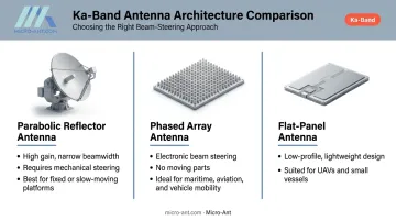
Not every platform needs, or can support, the same antenna architecture. Three designs dominate Ka-band deployments today.
Common Antenna Architectures for Ka-Band
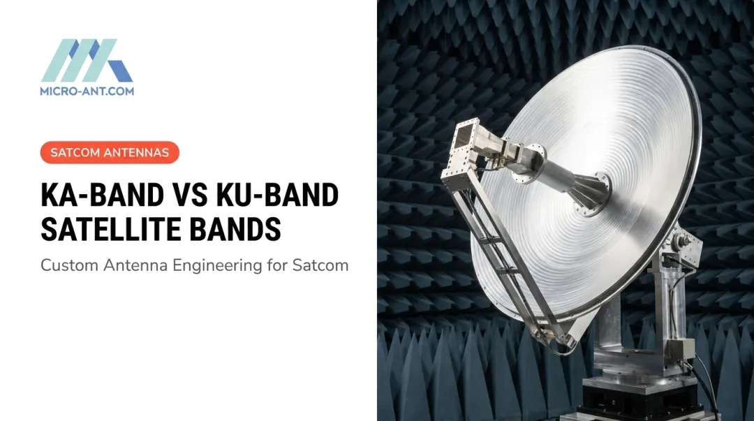
Parabolic reflector antennas remain the go-to for fixed or slow-moving installations that need high gain and narrow beamwidth. Their curved dish focuses signal energy precisely, but they require accurate pointing and mechanical steering.
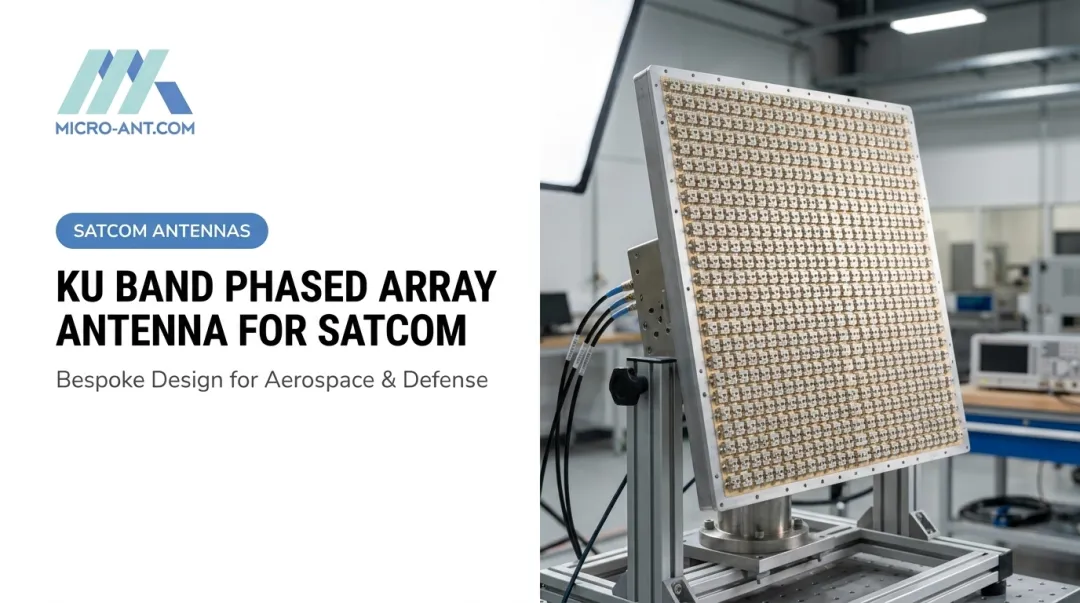
Phased array antennas solve the mobility problem. By electronically steering the beam, they eliminate moving parts entirely. That's a major advantage for maritime vessels, aircraft, and vehicles that need to track satellites while in motion.
Flat-panel, low-profile designs trade some gain for form factor. They're built for platforms where space and aerodynamics matter:
- UAVs and drones
- Small vessels and workboats
- Ground vehicles with limited roof clearance
Ultra-Wide Band Ka Innovations
Ultra-Wide Band Ka technology is a major recent advance, allowing a single terminal to roam across multiple satellite operators' frequency allocations without swapping hardware. Instead of being locked to one operator's slice of spectrum, the antenna covers the broader Ka SatCom range across LEO, MEO, and GEO constellations.
Micro-Ant's 3.5 GHz Ultra-Wide Band Ka Antenna System is a real-world example. Recognized as the 2022 Innovation of the Year, the system gives field terminals the flexibility to switch satellite networks without a truck roll or hardware replacement. Defense and commercial users operating across multiple regions or providers benefit directly from that flexibility.
Engineering Challenges in Ka-Band Design
Rain fade is the defining challenge at these frequencies. At a rain rate of 25 mm/h, Ka-band signals near 30 GHz can suffer roughly 5 dB/km of attenuation, compared to under 1.5 dB/km for Ku-band at 14 GHz. That's a substantial gap.
Engineers offset this with a few proven techniques:
- Adaptive Coding and Modulation (ACM): automatically adjusts data rates during signal degradation
- Uplink Power Control: systems maintain over 15 dB of dynamic range to hold the link during heavy rain, per NASA rain fade research
- Link margin design: clear-sky operations typically build in 4–5 dB of margin to absorb atmospheric fluctuations
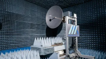
Manufacturing precision matters just as much. At millimeter-wave frequencies, tiny surface deviations produce measurable gain loss. That's why validation through near-field test chambers spanning 750 MHz to 40 GHz has become standard practice, confirming gain and radiation pattern performance before a system ever reaches the field.
Key Applications & Industries Using Ka-Band Antennas
Ka-band's throughput advantage shows up across several sectors, each with different operational demands.
Satellite broadband and HTS. Ka-band spot beams are the backbone of high-throughput satellite internet, bringing broadband to regions that fiber and cable never reached. Eutelsat's KONNECT VHTS platform demonstrates just how much capacity a single Ka-band satellite can now deliver.
Defense and government communications. Programs like the Wideband Global SATCOM constellation rely on Ka-band for tactical command and control. SATCOM-on-the-Move terminals, fielded under programs such as WIN-T, give mobile units secure, high-throughput connectivity without stopping to establish a link.
Maritime, aviation, and land mobility. This is where phased array and flat-panel designs earn their keep:
- Inmarsat's Fleet Xpress has connected over 14,000 vessels worldwide, pairing Ka-band with L-band backup for 99.9% availability
- Viasat's Ka-band in-flight connectivity delivers download speeds exceeding 20 Mbps on Dassault Falcon 7X and 8X aircraft
- Autonomous vehicle telemetry increasingly leans on compact Ka-band terminals for real-time data relay

Ka-Band vs Ku-Band: Key Differences & Which to Choose
Choosing between these two bands comes down to a handful of practical factors. Here's how they stack up:
| Factor | Ku-Band | Ka-Band |
|---|---|---|
| Frequency range | 12–18 GHz | 26.5–40 GHz |
| Antenna gain (comparable aperture) | ~23.8 dBi | ~26.75 dBi |
| Rain loss (heavy rain region) | ~2.5 dB | ~7.8 dB |
| Antenna form factor | Larger for equivalent gain | Smaller, more compact |
| Weather resilience | More stable | More sensitive to rain fade |
| Coverage pattern | Broader regional beams | Focused, high-capacity spot beams |
| Hardware cost | Lower, widely available | Higher, but declining |
Frequency and wavelength. Ka-band's shorter wavelength lets engineers build smaller antennas for the same gain — a real advantage when space or weight is limited.
Bandwidth and throughput. Ka-band supports up to 3.5 GHz of usable bandwidth in some allocations, far more than Ku-band's typically constrained spectrum. Micro-Ant engineered its Ultra-Wide Band Ka antenna system around this exact 3.5 GHz allocation, which explains why high-throughput satellite (HTS) operators lean so heavily on Ka-band for capacity-hungry applications.
Weather sensitivity. As the table shows, Ka-band takes a bigger hit in heavy rain. Ku-band remains the more forgiving option for regions with frequent severe weather.
Coverage pattern. Ku-band's wider regional beams suit broadcast and general coverage. Ka-band's tighter spot beams pack more capacity into a smaller footprint, ideal for HTS architectures.
Cost. Ku-band hardware is still cheaper and more established. Ka-band costs are dropping as adoption grows, but the gap hasn't closed entirely.
Decision Framework
Use this quick reference when specifying a system:
- High data demand, tolerant of weather risk? Ka-band, paired with ACM and adequate link margin
- Broad regional coverage, weather-sensitive region? Ku-band
- Tight budget, established infrastructure needed? Ku-band, at least for now
- Compact form factor is non-negotiable (UAV, small vessel)? Ka-band's smaller aperture wins
Why Choose Micro-Ant for Ka-Band Antenna Solutions
Micro-Ant has spent over 20 years designing and building custom antenna systems, delivering more than 1,000 bespoke products for defense, aviation, maritime, and land applications. The company's Jacksonville, Florida facility operates under AS9100:2016 and ISO 9001:2015 certifications, standards that matter when a customer's mission depends on the hardware working the first time.
The Ultra-Wide Band Ka Antenna System reflects that focus. By supporting multi-operator roaming across the full Ka SatCom range, it cuts down on the hardware swaps that slow field operations when a terminal moves between satellite networks. Combined with rugged construction built for demanding field conditions, the system keeps downtime to a minimum in the field.
Micro-Ant handles testing in-house, too. Micro-Ant's spherical and planar near-field test chambers cover 750 MHz to 40 GHz, allowing full gain and pattern validation before a system ships. For customers, that means:
- Faster turnaround than outsourced third-party testing
- Reduced travel time and cost for validation visits
- Verified performance data before a system ever leaves the facility
Frequently Asked Questions
What is a Ka-band antenna?
A Ka-band antenna is a satellite communication antenna engineered to operate in the 26.5–40 GHz range. It's known for supporting high-throughput, high-bandwidth data transmission across defense, broadband, and mobility applications.
Does the Ka-band require special antennas?
Yes. The higher frequency and shorter wavelength demand precision-engineered antennas, whether parabolic, phased array, or flat-panel, built with tighter manufacturing tolerances than lower-frequency bands require.
What is the difference between Ka-band and Ku-band antennas?
Ka-band offers higher bandwidth and throughput with a smaller antenna footprint but greater rain fade sensitivity. Ku-band offers broader coverage and more consistent performance in bad weather.
What frequency range does the Ka-band cover?
Ka-band spans 26.5 to 40 GHz, sitting directly above the K-band in the microwave spectrum. Some commercial systems reference an extended Ka-band downlink allocation starting near 17.7 GHz, distinct from the Ku-band's 12–18 GHz range.
Is Ka-band signal affected by rain fade?
Yes. Ka-band signals are more susceptible to rain fade and atmospheric attenuation than lower-frequency bands. Mitigation relies on adaptive coding and modulation plus careful link margin planning.
What industries rely on Ka-band satellite antennas?
Defense, satellite broadband providers, maritime, aviation, and government or intelligence communications all depend on Ka-band antennas for high-throughput, mission-critical connectivity.